For those of you who aren't familiar with it, the Arcam Delta Black Box 2 is a standalone DAC unit. It was one of the very first of its type, and uses a partially discrete custom S/P DIF receiver, a SAA7220 digital filter, a TDA1541A DAC and a discrete output stage.
Unfortunately the one I have no longer works. The problem is seems to be due the worst possible thing; a damaged custom IC in the S/P DIF receiver. It is getting the clock and data inputs that it should, the VCO is working and it outputs a system and bit clock, but no word clock and no serial data. Some of the external loopbacks have no activity where they should as well.
The power supplies and input data and clocks to it look good, so I'm stumped as to what else it could be. I've not yet given up the custom IC for dead yet, I'll keep probing around with my 'scope for a while.
Assuming that the custom IC is dead, I'm left with three options:
- Get a replacement custom IC (fat chance). Does anyone out there have an otherwise dead Black Box 1 or 2 (the custom IC is the same in both) which they are parting out?
- Get an off the shelf S/P DIF receiver PCB and replace the Black Box's original one. I was thinking of this or this, does anyone have any other suggestions?
- Make my own replacement receiver module. This would be the most satisfying solution, but the most expensive which kind of puts me off.
It's 9pm over here, so there's no good light to take photos, but I'll post some tomorrow. It's a really nice unit, so it'd be great to see it fixed. The service manual can be downloaded here.
Post #2 here... but I think you are way beyond that.
http://www.diyaudio.com/forums/digital-source/178418-polarity-meridian-500-transport-arcam-bb2.html
http://www.diyaudio.com/forums/digital-source/178418-polarity-meridian-500-transport-arcam-bb2.html
... but I think you are way beyond that.
Apparently not. I had forgotten that switch and completely overlooked it. As soon as I toggled it the whole digital section sprung to life like magic.
That wasn't the whole problem though, it still wouldn't make music. The rest of the problem was something I had suspected from the beginning; Arcam, like many British manufacturers, supplied -6VDC to the TDA1541A's VDD1, not -5VDC. This inevitably destroys the DAC IC, but usually after some time (ten years or so). I have no idea why they did this, they must have thought this gave some sort of performance increase.
Anyway, I've replaced the TDA1541A from my stack of them, and I'll change the resistor on the LM337 that supplies VDD1 to the TDA1541A so that it is outputting -5VDC.
Thanks heap for the suggestion Mooly, I could have battled for hours before remembering that!
Check the -15V supply to, there should be exactly 10V difference between the two at the DAC. You could also try an 22uF Oscon SP between the two rails.
Yes, now that it's fixed I'm off to bed. I had packed up when you first replied, but I though "We'll, it's worth a quick try".
They aren't. The first thing I did upon opening the unit was check the power supplies for voltage and ripple. VDD, VDD1 and VDD2 tested at 5, -6 and -15VDC, exactly what the manual says they should be. Again, I don't know why Arcam did this.
Check the -15V supply to, there should be exactly 10V difference between the two at the DAC. You could also try an 22uF Oscon SP between the two rails.
They aren't. The first thing I did upon opening the unit was check the power supplies for voltage and ripple. VDD, VDD1 and VDD2 tested at 5, -6 and -15VDC, exactly what the manual says they should be. Again, I don't know why Arcam did this.
Philips used -6V in the CD960 (and perhaps others) maybe Arcam copied them who knows. I always use a heatsink on the DAC and make sure the -15 and -5 and tied together anyway.
Alright, here's the pictures I said I'd post:
a) The Black Box on top of the transport I'm currently using, a Mission PCM II. Nice match visually.
b) The isolation cutouts in the mainboard that minimize vibration in the DAC IC. At the moment I'm just using a low grade R1 TDA1541A, when I've changed the -6V rail to -5V I'll install an S1.
c) The mainboard. I haven't finished replacing the electrolytic capacitors, dark blue and brown are new, light blue and black are yet to be replaced.
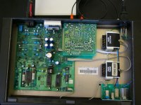
d) The whole thing from above. Mainboard at the left, input board at top centre, transformers at the right. The silver case at the top of the picture is my low noise clock which feeds the PCM II.
a) The Black Box on top of the transport I'm currently using, a Mission PCM II. Nice match visually.
b) The isolation cutouts in the mainboard that minimize vibration in the DAC IC. At the moment I'm just using a low grade R1 TDA1541A, when I've changed the -6V rail to -5V I'll install an S1.
c) The mainboard. I haven't finished replacing the electrolytic capacitors, dark blue and brown are new, light blue and black are yet to be replaced.
d) The whole thing from above. Mainboard at the left, input board at top centre, transformers at the right. The silver case at the top of the picture is my low noise clock which feeds the PCM II.
Attachments


- Status
- Not open for further replies.
- Home
- Source & Line
- Digital Source
- Arcam Black Box 2 Repair