Wow there.
The Armstrong 525 (5 series) are not the same as the 625 (6 series). The 5 series use(d) PNP Germanium output devices type AL102. These are prone to leakage as they age so be careful. Note also they have a Negative HT rail with the Positive returned to ground. Circuit here: http://ukhhsoc.torrens.org/makers/Armstrong/500_and_400_ranges/Circuit_Diagrams/521diagram.pdf
@legin reltub,
It would be a better idea to either start another thread specifically for the 525 or maybe pop over to UK Vintage Radio Repair and Restoration (UK Vintage Radio Repair and Restoration Discussion Forum) where there is possibly more experience of the Armstrong amps?
Yes start another thread. Germanium amps are completely different beasts than silicon. I stayed with vacuum tubes in the germanium era. So did Ford motor co car radios, my introduction to electronics. My one germanium Olson AM radio was ****, drifted off station as it warmed up.
My browser sees your 521 diagram as insecure and won't download it. Signing out at this point.
My browser sees your 521 diagram as insecure and won't download it. Signing out at this point.
Last edited:
Thanks for the reply, bit to technical for me, but I get the idea one of the capacitors has had it, swapped them over with box of spare caps. No diference. Could it be one of the AL102 transistors on that channel? I have some new transistors coiming but can not find any 1250uf 35vdc caps.
could mean a trip to the repair shop 🙁
Anyway life goes on. Thanks again
could mean a trip to the repair shop 🙁
Anyway life goes on. Thanks again
Thanks @Alan4411, misssed your comment, I'll take a look at the Vintage radio site. I was aware that they are totally different with the 625 having silicone transistors but I thought my problem with the constant thudding on the bass and a 25vdc on one of the speaker terminals could have been a generic issue, possible with any amp? I did read something to do with the AL102 transistors possible leaking or may have been transistors in general and causing this issue and also read it could be bad capcitors. Anyway time to fire up the amp that works 🙂
Hi there,
I like the armstrong amps very much, and actually have 3 of them - 621, 625 and another 621 which I found recently and buy from a guy who has several of them in a storage.
In fact, this last one is a brand new amp, which amazingly waits for 49 years to be opened for the first time today. From Britain to Australia, and finally arrive in Bulgaria to be part of my collection! It sounds just brilliant out of the box! Its so amazing. My question is if I can get some advices from you? What do you think, should I check some parts, which could be important, or should I replace some parts, as long as the amp sounds as good as it shoud be? Im afraid I might damage the unit, since Its been in a box for the 5 decades. Thanks.
Attachments


I'd just admire a NOS 621 on the shelf. Maybe operate briefly to show friends or something. Germanium transistors were not long life components, just the newest thing on the block in 1962(?) My employer tried germanium drivers briefly mid 60's then went back to vacuum tubes (5221) for rough rider geophysics sine wave generators until ~1976. The data recording trucks used to come in for repair with broken springs, but the tubes would be okay.
Those screw top caps had enough water they probably survived, but the axial lead electrolytic caps I'd give an ESR test before operating at full temperature. Rubber cap seals can crack on the shelf, or not, depending on what grade rubber the manufacturer used. No telling how long the life would be from appearance. A cracked seal cap will work fine for a few hours until the water evaporates out after warm up.
I'd imagine the sound to be okay from looking at the schematic diagram, but nothing to brag about. Pick up a used PA amp or something for 14 hour a day use. I scored a QSC CX302 for $106 this month on ebay: worked out of the box. .05% HD @ 325 w/ch 4 ohms. @ 25 years may need caps to get up to full wattage, but I listen @ 1 watt mostly.
Last edited:
Sorry for the delay guys @indianajo
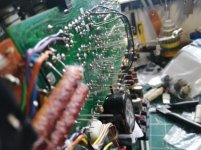
So yes i did infact do a complete rebuild of the 621!
I ended up doing a full electrolytic replacement, i even upgraded the power supply somewhat (part changes).
The 625 i used for spares was the updated and later version which had better parts like the pots (all alps) same with the preamp board, any noisy transistors were replaced with equivalents.
I took all the good parts and rebuilt the 621 and it came out splendidly, i even measured the performance and i have to say it did better than expected.
This has been runninh for a year now with no issues, sounds wonderful and will last another 30 years.

Before

After


So yes i did infact do a complete rebuild of the 621!
I ended up doing a full electrolytic replacement, i even upgraded the power supply somewhat (part changes).
The 625 i used for spares was the updated and later version which had better parts like the pots (all alps) same with the preamp board, any noisy transistors were replaced with equivalents.
I took all the good parts and rebuilt the 621 and it came out splendidly, i even measured the performance and i have to say it did better than expected.
This has been runninh for a year now with no issues, sounds wonderful and will last another 30 years.
Before
After
Attachments


I know this is an old thread but I hope someone may be able to give me some advice. I have a 621 amp which I bought secondhand. After working through and repairing a few silly faults caused by minor component failures, and replacing a couple of noisy small signal transistors I decided to measure the distortion just to see how it compares with more modern equipment and to prove to myself all was in order. And it was terrible 0.5% at 1KHz and 1W. First thing I noticed was that swinging the balance control or unplugging one speaker immediately halved the distortion. So it appeared to be current related. My first thought was that the 0V between the main pcb and the smoothing cap was high resistance. I checked this and all was OK. In the end I detached the front end of the power amp 0V (by cutting the pcb) and connected this directly to the 0V star point. And the problem has gone, in fact the amp measures around 0.01% to 0.005% so very good indeed for such an old design (using the tape monitor input) and roughly in line with SPICE models. So... am I going crazy? Surely no amps would have been sold with this kind of fault and certainly the reviews post circa 0.08% figures of which approx 0.06% is due to the preamp. And finally, if anyone has a spare Armstrong illuminated badge from the front panel (it just clips in) I would be happy to purchase one from them. Thanks!
I have had several conversations with Jim Lesurf over this issue and he has been very kind despite being unwell.
He advised that build standards did vary and much information has been lost, as he joined Armstrong near the end of the 600 series production. Number one candidate is the thermal delay switch which is known to fail frequently and others have commented on. I had checked this early on and it appeared to be working, but I have now removed it and upgraded the rectifiers with little result. The problem IMO is caused by 0v output stage current injecting noise into the power amp from the output stage, This is exacerbated by the lack of decoupling on the power amp pcb and the relatively long power feed.
Love to hear anyone else's comments and theories. But seems this could be a major reason why these old capacitor coupled amps sound different to the later direct coupled amps. Its just more difficult to get rid of 0v related distortion products.
BTW I have no idea how to PM anyone on this forum, or indeed if its turned on for me, So hoping you can contact me! Please let me know.
Your experiments post 29 are very interesting. Having only schematics to go by, and no actual armstrongs sold in US, I'll have to take your word for it. 0.5% HD was quite respectable in 1964? They probably just stopped designing right there and started figuring out how to make some money with these. But dodgy ground paths are something that a lot of knowledge has been gained since then. I mean the competition were dynaco & SWTC that oscillated & resistors burst into flame sometimes, and that UK brand that started with an S that didn't even come with heatsinks on the output transistors.
The capacitor coupled versus direct connect argument is a sideshow. I found my dynakit ST120 with capacitor out a bit weird sounding as original, but an almost the same Apex AX6 with fewer parts is quite nice sounding. It is all in the details. 40636 outputs on Armstrong schematic with 400 khz Ft limited high frequency response, but same layouts with 2 mhz Ft TIP3055, 2n3773, or MJ15015 are fine with the 50 mhz drivers RCA was selling in 1966 (2n5320/22, previously known as 40409/40410). 1966 small signal transistors were hit & miss on noise. from factories that were not sealed against dirt, full of bond operators shedding dead skin and hair. Low noise 1970 transistors were tested & selected for noise performance, whereas a 2018 MPSA06/56 or 2n5401/5551 come from the line squeaky clean by modern process control. Positive pressure clean room fab with no operators but maintenance men in bunny suits.
The capacitor coupled versus direct connect argument is a sideshow. I found my dynakit ST120 with capacitor out a bit weird sounding as original, but an almost the same Apex AX6 with fewer parts is quite nice sounding. It is all in the details. 40636 outputs on Armstrong schematic with 400 khz Ft limited high frequency response, but same layouts with 2 mhz Ft TIP3055, 2n3773, or MJ15015 are fine with the 50 mhz drivers RCA was selling in 1966 (2n5320/22, previously known as 40409/40410). 1966 small signal transistors were hit & miss on noise. from factories that were not sealed against dirt, full of bond operators shedding dead skin and hair. Low noise 1970 transistors were tested & selected for noise performance, whereas a 2018 MPSA06/56 or 2n5401/5551 come from the line squeaky clean by modern process control. Positive pressure clean room fab with no operators but maintenance men in bunny suits.
Last edited:
Hi Indianajo, the amp dates from 1972/3 period so the transistors are not too bad, I replaced a couple of noisy small signal ones. The published distortion was 0.08% in the spec sheet. So pretty good for the time, and the reviews bear this out. The engineers at Armstrong were pretty competent, so I was surprised when 'my' amp showed such high figures and that the position of the balance control (or disconnecting one speaker) made such a drastic difference.. I agree that AC/DC coupling should not make much difference in itself, but I had not considered the 0V noise issues before. My solution works fine BUT I can't believe the amps were sold like this, hence my post, as I felt I might be missing something. Thank you for your interest!
- Home
- Amplifiers
- Solid State
- Armstrong 621 and 625 complete rebuild