Hi!
For this project I'll be using 40 pcs of micro speaker (102dB@10cm) spaced at 9.1mm C-t-C to emulate a ribbon.
The "ribbon" will be mounted to the throat of a custom ATH4 horn flare. I will use an 8PR200 for bass.
To improve the vertical wavefront / directivity I will add active shading to each speaker or group of speakers.
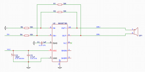
Each micro speaker will be driven by its own MAX9718A amplifier.
https://www.mouser.co.uk/ProductDetail/Maxim-Integrated/MAX9718AETB+T?qs=1THa7WoU59FvOsgrnnj7bg==
It will be straight forward to taper the levels vertically as the MAX9718A exposes adjustable gain.
For delay I may try wrapping the appropriate allpass/bandpass around the MAX9718A or alternatively use a few LME49721.
More to follow.
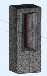
polars
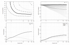
horiz at 45deg no shading

vert at 5deg no shading

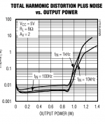
test board

For this project I'll be using 40 pcs of micro speaker (102dB@10cm) spaced at 9.1mm C-t-C to emulate a ribbon.
The "ribbon" will be mounted to the throat of a custom ATH4 horn flare. I will use an 8PR200 for bass.
To improve the vertical wavefront / directivity I will add active shading to each speaker or group of speakers.
Each micro speaker will be driven by its own MAX9718A amplifier.
https://www.mouser.co.uk/ProductDetail/Maxim-Integrated/MAX9718AETB+T?qs=1THa7WoU59FvOsgrnnj7bg==
It will be straight forward to taper the levels vertically as the MAX9718A exposes adjustable gain.
For delay I may try wrapping the appropriate allpass/bandpass around the MAX9718A or alternatively use a few LME49721.
More to follow.

polars

horiz at 45deg no shading

vert at 5deg no shading

test board


Last edited:
So 20 segments per speaker, c-c 9mm -> 18cm length. Mated to s 8" = 18cm woofer. Nice.
Re delay... if configure as delayed pairs, you will need 10 channels per speaker. Is that 0,5ms for the latest segment approx?
I understand you are trying for "analog delay" - how about digital?
How will you make the ribbon segment drivers?
Looking forward to follow the executing with interest.
//
Re delay... if configure as delayed pairs, you will need 10 channels per speaker. Is that 0,5ms for the latest segment approx?
I understand you are trying for "analog delay" - how about digital?
How will you make the ribbon segment drivers?
Looking forward to follow the executing with interest.
//
So 20 segments per speaker, c-c 9mm -> 18cm length. Mated to s 8" = 18cm woofer. Nice.
Re delay... if configure as delayed pairs, you will need 10 channels per speaker. Is that 0,5ms for the latest segment approx?
I understand you are trying for "analog delay" - how about digital?
How will you make the ribbon segment drivers?
Looking forward to follow the executing with interest.
//
I'm not sure I need that amount of delay. I think i just need to electrically delay the wave front to exit perpendicular to the top and bottom surfaces. In this case roughly 45mm or 130us. I may well be wrong.
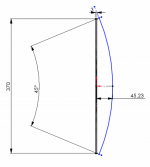
Last edited:
It does make me kinda curious what this micro speaker is. Things like sensitivity etc...
If you scour the datasheets you can find micro speakers from the likes of Challenge. Flat from 500 to 20k, 98dB @ 10cm @ 1W in a sealed 5cc box.
https://www.digikey.co.uk/en/products/detail/challenge-electronics/CS40-01P50-04-1X/13557619
I'm not using this one though. 🙂
Last edited:
Almost finished the 20 speaker "ribbon emulator"
I'll put the speakers on the rear of the board. This will end up 25mm x 210mm.
The large unit at the bottom is a BNX027 EMI filter
https://www.mouser.co.uk/datasheet/2/281/QNFH9101-1131754.pdf
I have a few from a previous project. They work well.
The two LME49721 form a HP high pass and buffer.
Could make for an interesting desktop pencil speaker!
This first version will not have any shading, just a vertical bank of drivers with 16W of amps and high pass filter.
I need to make 1mm slots in the PCB too so the rear of the speakers can breath into a back cavity. Getting very tight but cool.
Last edited:
Wow, neat project! I hope it's successful because custom integrated PCB audio is inexpensive with those companies that print and populate prototype boards. I looked at using them for FreeDSP boards.
It would be interesting to simulate the actual driver size and spacing to see how closely it resembles a single source, to what frequency.Yes, 25mm x 210mm should be OK.
My ASUS laptops have speakers that look quite similar in shape.
If we say the effective dia is 7mm, will start to beam I think at
f = (2 * 343) / (3.14 * 0.007) = 31.2kHz
f = (2 * 343) / (3.14 * 0.007) = 31.2kHz
Last edited:
It is quite simple in AKABAK or ABEC (Not in Ath) to see the difference between a solid radiator diaphragm and one composed of separate parts with gaps in between. These may be small enough to be irrelevant but sometimes things don't work out the way you imagine.If we say the effective dia is 7mm, will start to beam I think at
f = (2 * 343) / (3.14 * 0.007) = 31.2kHz
Maybe, when looking at directivity it isn't really necessary. If you know the size of the speaker radiating element and the gap in between I can check for you to see if it has any effect. If it did the diaphragm mesh could be changed in the ABEC sim without too much trouble.
- Home
- Loudspeakers
- Multi-Way
- array of micro speakers with shading in ATH4 horn