NJM8830 looks like a good little mobile +/-5V opamp with +/-100mA
https://www.mouser.com/datasheet/2/294/NJM8830_E-2953374.pdf
https://www.mouser.com/datasheet/2/294/NJM8830_E-2953374.pdf
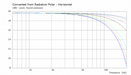
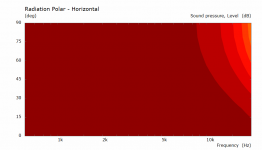
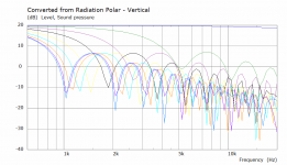
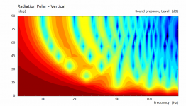
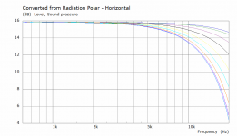
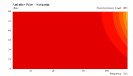
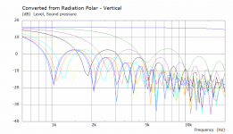
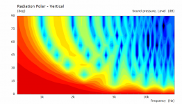
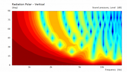
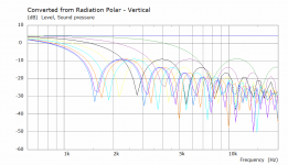
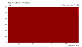
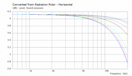
The difference between them is pretty small, both look quite bad outside the narrow vertical window but that is quite normal and in the polar curves it is because only one of the measurement points is within the usable window.
Attachments
")
All a bit tiny down there. Sanity check on the filter network and buffer.
I'm connecting the OUTPUT of one LME49721 to 20 parallel MAX9718A amplifers with 10k input resistors.
The LME49721 output current is 9mA max at 5V supply. Is my OUTPUT buffer arrangement sufficient?

Input filter network

MAX9718A amplifer

filter network repsonse, group delay and phase

I'm connecting the OUTPUT of one LME49721 to 20 parallel MAX9718A amplifers with 10k input resistors.
The LME49721 output current is 9mA max at 5V supply. Is my OUTPUT buffer arrangement sufficient?
Input filter network
MAX9718A amplifer
filter network repsonse, group delay and phase
Check out this patent: https://patentimages.storage.googleapis.com/eb/b2/a3/440760889d293e/US20120328140A1.pdfI'm not sure I need that amount of delay. I think i just need to electrically delay the wave front to exit perpendicular to the top and bottom surfaces. In this case roughly 45mm or 130us. I may well be wrong.
View attachment 1106777
cool project!


further dim tweaks and we are nearly there. I'd like to sim the speaker as a system next.
@sheeple provided a process. I will give that a try.
https://www.diyaudio.com/community/...-design-the-easy-way-ath4.338806/post-7169375


@sheeple provided a process. I will give that a try.
https://www.diyaudio.com/community/...-design-the-easy-way-ath4.338806/post-7169375
Catching up on VituixCAD features. The optimizer is eye watering.
https://www.htguide.com/forum/forum...niques/42827-vituixcad-v2?p=835533#post835533
https://www.htguide.com/forum/forum...niques/42827-vituixcad-v2?p=835533#post835533
I replicated the report settings as best I could to match the ATH4 CE260 report for a A/B comparison.
I have left another batch running over night. Maybe I'll get closer still to the CE260 performance.
* I have not normalised to 10deg - will do that in the morning.


I have left another batch running over night. Maybe I'll get closer still to the CE260 performance.
* I have not normalised to 10deg - will do that in the morning.
Last edited:


The difference between them is pretty small, both look quite bad outside the narrow vertical window but that is quite normal and in the polar curves it is because only one of the measurement points is within the usable window.
How about 40pcs split vertically, active area x=4.8mm y=3.8mm with spacing 5.7mm in Y.
Not as loud and tighter vertical windowHow about 40pcs split vertically, active area x=4.8mm y=3.8mm with spacing 5.7mm in Y.
Attachments
Don't get discouraged, this is the nature of arrays, they do not behave the same way as a single driver.
You might think that 5 degrees is the vertical window but it isn't, when you move up or down within the bounds of the lines ends the response vertically is exactly the same.
For example I moved the observation point 70mm higher and the vertical graph is the same. This might not seem right but it is.
I’m intrigued by small amps with dsp
This NAU83G10/20 with Klippel Controlled Sound technology looks interesting!
https://www.nuvoton.com/export/resource-files/DS_NAU83G10_ProductBrief_Rev1.1.pdf
https://audioxpress.com/news/klippe...with-integrated-kcs-speaker-control-algorithm
https://www.klippel.de/fileadmin/klippel/Files/Know_How/Literature/Papers/Nuvotons Smart Amp Evaluation Platform with Klippel Controlled Sound.pdf
Last edited:
Today I designed a dev board for an old PWM dsp from D2 Audio / now Renesas.
https://www.renesas.com/us/en/produ...lligent-digital-amplifier-and-sound-processor
I have 12 channels of PWM high & low buffered output (SN74LVC2G34) at 5.5V. SNR>110dB & THD+N <0.01% .
MCU for initial programming to the dsp memory plus volume & tilt pot.
In theory I could use the PWM high & low buffered outputs as speaker low output test drivers (25ma) with suitable filtering.


https://www.renesas.com/us/en/produ...lligent-digital-amplifier-and-sound-processor
I have 12 channels of PWM high & low buffered output (SN74LVC2G34) at 5.5V. SNR>110dB & THD+N <0.01% .
- 2 x I2S input
- 2 x SPDIF input
- 1 x SPDIF output
- protection inputs
- 90mm x 120mm
MCU for initial programming to the dsp memory plus volume & tilt pot.
In theory I could use the PWM high & low buffered outputs as speaker low output test drivers (25ma) with suitable filtering.
Last edited:
I've been looking at tiny mosfets with low rdson / qg
I think this may suit for a 5W output amp
NTTFD4D0N04HL
12-WQFN (3.3x3.3)
https://www.onsemi.com/pdf/datasheet/nttfd4d0n04hl-d.pdf
I think this may suit for a 5W output amp
NTTFD4D0N04HL
12-WQFN (3.3x3.3)
https://www.onsemi.com/pdf/datasheet/nttfd4d0n04hl-d.pdf
Sanity check using the NTTFD4D0N04HL on a tiny board ( 50mm x 19mm )
Max RDS(on) = 7mΩ at VGS = 4.5V
Rise and fall pretty good.
As this will be for "ribbon emulator" frequencies I am proposing a half bridge with single pole high pass bias network to improve PSRR.
Not sure about the comps or vals yet. I'll sleep on it.
Comments welcomed!


Max RDS(on) = 7mΩ at VGS = 4.5V
Rise and fall pretty good.
As this will be for "ribbon emulator" frequencies I am proposing a half bridge with single pole high pass bias network to improve PSRR.
Not sure about the comps or vals yet. I'll sleep on it.
Comments welcomed!
Last edited:
- Home
- Loudspeakers
- Multi-Way
- array of micro speakers with shading in ATH4 horn