Hello everybody.
Stumbled upon this forum while doing some googling to find answers to my question.
So I got a simple DIY CMOY amp from a friend. Just an average project, nothing special. I kinda like the sound. Problem is, it's not very powerful.
There's no problem if I use it with IEMs, or easy to drive headphones, like my AD700, but when I tried it with my everyday headphone, the HE400, this amp falters badly. Somewhere around 12 o'clock of the volume knob, it started to clip north and south. Between 1 o'clock to 5 o'clock (max), I got no volume gain whatsoever, it's like the pot malfunctioned at that region. I suspect it got not enough current to run HE400 properly. HE400 is 35ohms, 93dB/mW.
This is some pictures of the amp in question:
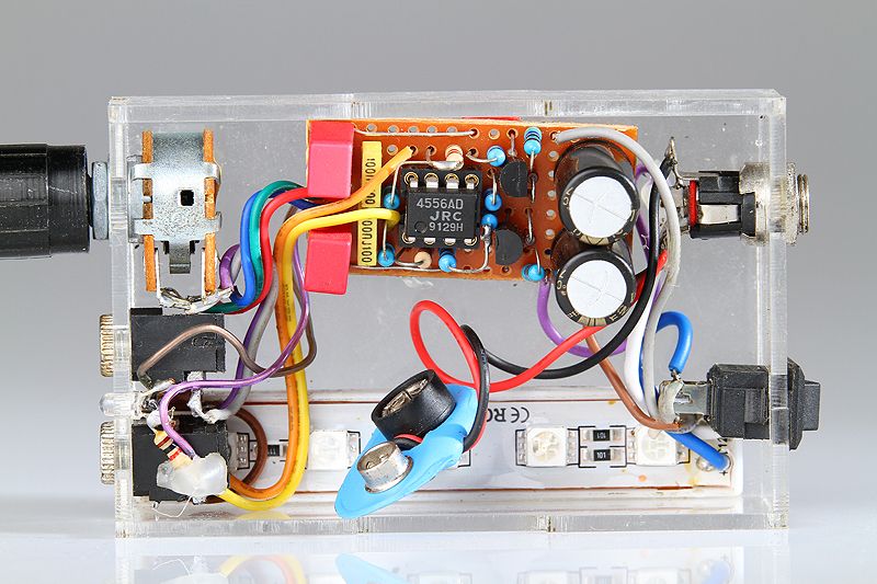
It can be used with a 9V battery, but I'm using an external power supply, 9V 2A.


This is the close-up of the board. It's a simple DIY project using breadboard, so it's a bit of rat's nest on the other side.
My question is, are there any ways/mods I can do to make it output more power or current? I can handle soldering gun, but I can't make head or tail out of electronic circuits. So I'm hoping for simple 'idiot's way' answers, i.e. 'change this capacitors to that type of capacitors', or something like that.
Sorry for my English, it's not my mother tongue.
Thank you in advance.
Stumbled upon this forum while doing some googling to find answers to my question.
So I got a simple DIY CMOY amp from a friend. Just an average project, nothing special. I kinda like the sound. Problem is, it's not very powerful.
There's no problem if I use it with IEMs, or easy to drive headphones, like my AD700, but when I tried it with my everyday headphone, the HE400, this amp falters badly. Somewhere around 12 o'clock of the volume knob, it started to clip north and south. Between 1 o'clock to 5 o'clock (max), I got no volume gain whatsoever, it's like the pot malfunctioned at that region. I suspect it got not enough current to run HE400 properly. HE400 is 35ohms, 93dB/mW.
This is some pictures of the amp in question:
It can be used with a 9V battery, but I'm using an external power supply, 9V 2A.
This is the close-up of the board. It's a simple DIY project using breadboard, so it's a bit of rat's nest on the other side.
My question is, are there any ways/mods I can do to make it output more power or current? I can handle soldering gun, but I can't make head or tail out of electronic circuits. So I'm hoping for simple 'idiot's way' answers, i.e. 'change this capacitors to that type of capacitors', or something like that.
Sorry for my English, it's not my mother tongue.
Thank you in advance.
The 9 volt supply is one of the limitations here. It means the opamp can only swing around -/+4 volts at best, and into 35 ohm, a lot less than that.
Things you could try would be increasing the supply. The opamp can take up to 36 volts in total but make sure any caps and other parts are OK at that voltage. You could also add a small series output resistor to the headphone feed (or increase what is there) along with an increase in supply.
Things you could try would be increasing the supply. The opamp can take up to 36 volts in total but make sure any caps and other parts are OK at that voltage. You could also add a small series output resistor to the headphone feed (or increase what is there) along with an increase in supply.
The 9 volt supply is one of the limitations here. It means the opamp can only swing around -/+4 volts at best, and into 35 ohm, a lot less than that.
Things you could try would be increasing the supply. The opamp can take up to 36 volts in total but make sure any caps and other parts are OK at that voltage. You could also add a small series output resistor to the headphone feed (or increase what is there) along with an increase in supply.
Hello, thank you very much for the answer, but it's kinda 'greek' to me, as in I don't understand much.
What I (kinda) can understand is:
- Instead of using 9V, it's better to use higher input voltage. Will 24V be okay? I think I can get my hands on a 24V power supply easily.
- I have to make sure the capacitors can handle 24V. Which other parts I should check the voltage limit?
- I'm guessing the power indicator LED will fry at 24V? I tried measuring the voltage while it's lit, it's at 3V. So I should get a resistor to drop the voltage to 3V from 24V?
- I don't really understand this part:
You could also add a small series output resistor to the headphone feed (or increase what is there)
So I should add resistor(s) to the amp audio out?
Thank you very much, and sorry, I don't have much knowledge in electronics other than soldering cables.....
24 volts DC would be fine. The caps to check are those large electrolytic can type ones, the voltage will be marked on the wrapper. All the others take way over 24 volts.
Your CMOY appears to have two transistors and possibly a couple of diodes ? near them. If you can point me to the circuit diagram for this (there are lots of CMOY variations) then I can tell you exactly what they are and whether it would work with no other changes. I think they will be to derive what is called a "virtual ground" from the single rail supply.
Adding a resistor can make the load the opamp sees easier to drive... but I think tbh your main problem here is a lack of supply, 9 volts just isn't enough.
The really quick try is to just use two 9V batteries in series which will double your voltage. And all you need to do is change how the "new" battery connects to the old 9V single battery connector. (Just make sure all the capacitors can handle 18V.)
the circuit diagram would help - likely there are current limit R that don't play well with low Z, low sensitivity phones
the O2 project amp doubles up those op amps for more output current
the O2 project amp doubles up those op amps for more output current
Use balanced/inverted output configuration, to almost double the output swing.
But at that point it's no more a cmoy 😀
But at that point it's no more a cmoy 😀
24 volts DC would be fine. The caps to check are those large electrolytic can type ones, the voltage will be marked on the wrapper. All the others take way over 24 volts.
Your CMOY appears to have two transistors and possibly a couple of diodes ? near them. If you can point me to the circuit diagram for this (there are lots of CMOY variations) then I can tell you exactly what they are and whether it would work with no other changes. I think they will be to derive what is called a "virtual ground" from the single rail supply.
Adding a resistor can make the load the opamp sees easier to drive... but I think tbh your main problem here is a lack of supply, 9 volts just isn't enough.
The really quick try is to just use two 9V batteries in series which will double your voltage. And all you need to do is change how the "new" battery connects to the old 9V single battery connector. (Just make sure all the capacitors can handle 18V.)
the circuit diagram would help - likely there are current limit R that don't play well with low Z, low sensitivity phones
the O2 project amp doubles up those op amps for more output current
Thank you for the answers.
I don't have the diagram, and I lost contact with my friend who built it, so asking him for a diagram is a no go.
I took a picture of the back of the PCB. Because it's a simple DIY with a breadboard, it's a rat's nest. I don't know if anybody can make a meaning out of it:

The picture has been flipped, so left stays left, and right stays right.
The capacitors it's using are 220uF 16V, so I guess 24V is a no go, unless I replace the caps. I tried plugging a 12V 1A power supply, and true enough, it got wayyyy better. It still clips near the max volume, especially on low frequencies like kicks, but it sure is better and more resilient to clippings on lower volumes. The IC got a bit warm to touch. Not hot, just warmer (with 9V, I can't feel any temperature difference)
I scrounged at my tidbits box, and found some capacitors that are 470uF 25V. Can I just use them to replace the original capacitors?
Use balanced/inverted output configuration, to almost double the output swing.
But at that point it's no more a cmoy 😀
It's greek to me, I don't really understand...
In the usual configuration, you have one opamp getting signal on the + input, and feedback on the - input, generating an in-phase output, with the other side of the output being GND.
Now if instead of GND, you use another opamp, with the input signal fed to the - input, and feed its output in replacement for GND, you double the output swing, given same rail voltage.
But, unless you go SMD PCB, you are unlikely going to fit this into a typical cmoy case.
Now if instead of GND, you use another opamp, with the input signal fed to the - input, and feed its output in replacement for GND, you double the output swing, given same rail voltage.
But, unless you go SMD PCB, you are unlikely going to fit this into a typical cmoy case.
Its not possible to figure out exactly whats what from the picture. The transistors form a virtual ground... its a standard circuit, its just the detail that is difficult to fill in.
A bit of googling from the CMOY site... I'll bet its this variation, 3rd picture up from the bottom.
Virtual Ground Circuits
Your two caps should share the supply equally. If you measure the actual voltage across each then you should see 6 volts (running on a 12 volt supply). Does that mean you can run it on 24 volts as it is 😱 As long as it all works correctly then yes. If a fault occurred that allowed either cap to see more than 16 volts then you would damage the cap... and they can go pop if there is enough current available from the supply 😀
So its up to you. I would advise changing those 4.7k resistors to perhaps 10k although it should work just fine as it is, just a bit wasteful of power.
The heating of the IC is normal and you could be feeling the other parts getting slightly warm too.
Edit... the CMOY site if you are interested,
http://tangentsoft.net/audio/cmoy/
In the usual configuration, you have one opamp getting signal on the + input, and feedback on the - input, generating an in-phase output, with the other side of the output being GND.
Now if instead of GND, you use another opamp, with the input signal fed to the - input, and feed its output in replacement for GND, you double the output swing, given same rail voltage.
But, unless you go SMD PCB, you are unlikely going to fit this into a typical cmoy case.
The problem with this is that the headphones share a common ground (the inner part of the plug). Unless you separate the wires to each earpiece you can't run a bridge configuration.
Since this amp works, perhaps you might like to leave it unmodified and build a new one? Sounds like you have some components. You can borrow the 4556 from the existing amp since it's in a socket, or order from ebay. All you really need is the same, or a similar design built to work with a bigger supply voltage.
Its not possible to figure out exactly whats what from the picture. The transistors form a virtual ground... its a standard circuit, its just the detail that is difficult to fill in.
A bit of googling from the CMOY site... I'll bet its this variation, 3rd picture up from the bottom.
Virtual Ground Circuits
Your two caps should share the supply equally. If you measure the actual voltage across each then you should see 6 volts (running on a 12 volt supply). Does that mean you can run it on 24 volts as it is 😱 As long as it all works correctly then yes. If a fault occurred that allowed either cap to see more than 16 volts then you would damage the cap... and they can go pop if there is enough current available from the supply 😀
So its up to you. I would advise changing those 4.7k resistors to perhaps 10k although it should work just fine as it is, just a bit wasteful of power.
The heating of the IC is normal and you could be feeling the other parts getting slightly warm too.
Edit... the CMOY site if you are interested,
How to Build the CMoy Pocket Amplifier
So I took the plunge before reading your reply, and replaced the original 220uF 16V capacitors with my salvaged (from another project) 470uF 25V capacitors. Apparently they're even the same type, Elna Cerafine.
With the new capacitors in place, plugged with 12V power supply, it sounds so much better. The clippings are almost 100% gone. I'm still scrounging for higher voltage power supply, or I'll get one from the store later.
I found something strange, though. I got a cheap DMM that can measure AC voltage. I know it's not very accurate, but it's all I got. So I played a 1kHz sine tone, and measured the original signal coming out of my ipad. It read 0.35. When I plugged it to the amp, and measured the amp's output at max volume, it also read 0.35. It's the same whether I use a 9V or 12V power supply. Doesn't this mean the amp doesn't do any voltage/loudness gain? Is it normal (for CMOY amps)?
Since this amp works, perhaps you might like to leave it unmodified and build a new one? Sounds like you have some components. You can borrow the 4556 from the existing amp since it's in a socket, or order from ebay. All you really need is the same, or a similar design built to work with a bigger supply voltage.
Seems like a good idea, but I can't really make heads or tails out of electronic circuit diagrams. If it's a ready printed PCB, with all the components and instructions ready, I might be able to build one, kinda like assembling model kit toys. With blank breadboards, it's beyond my reach, though.
And of course, thank you for all the answers. I don't really understand much other than assembling and soldering parts. 🙂
Many DVM's aren't ideal for low AC measurement and even more so at higher frequency but that said....
The gain of the opamp is independent of the supply voltage. As long as the supply is high enough for the opamp to deliver its "asked for" output then changing the supply makes zero difference.
The voltage gain of the CMOY (the one in the second link I posted under "Schematic") is shown on the diagram as being 11. That is calculated by looking at the value of the two feedback resistors which are a 10k and a 1k. The gain is (10k+1k)/1k which is 11. You might look and see what actual values yours has compared to the diagram.
The O2 headphone amp would be a great project if you can solder neatly. Its streets ahead of the CMOY in every respect.
http://www.diyaudio.com/forums/headphone-systems/193977-objective2-o2-headphone-amp-diy-project.html
Many DVM's aren't ideal for low AC measurement and even more so at higher frequency but that said....
The gain of the opamp is independent of the supply voltage. As long as the supply is high enough for the opamp to deliver its "asked for" output then changing the supply makes zero difference.
The voltage gain of the CMOY (the one in the second link I posted under "Schematic") is shown on the diagram as being 11. That is calculated by looking at the value of the two feedback resistors which are a 10k and a 1k. The gain is (10k+1k)/1k which is 11. You might look and see what actual values yours has compared to the diagram.
The O2 headphone amp would be a great project if you can solder neatly. Its streets ahead of the CMOY in every respect.
http://www.diyaudio.com/forums/headphone-systems/193977-objective2-o2-headphone-amp-diy-project.html
Well, I guess I've done all I can for this small DIY amp then. It got good sound, but in term of loudness, even my old Fiio E6 is way louder than this amp.
I'll take a look at the O2 amp project, and see if I can muster enough courage to start it, being a novice in electronic and all.
Again, thank you very much for all the answers.
Well, I guess I've done all I can for this small DIY amp then....
Not so soon comrade, this is diyaudio!
First use split power supply +/-5V for h/p with less than 56 Ohms impedance & +/-9V for anything above 100 Ohms. Virtual gnd is the bottleneck of this design, limiting the max current capability of JRC4556. Use 120Hz signal for testing purpose. Use this http://nwavguy.blogspot.in/2011/07/cmoy-with-gain.html guide for selecting proper component values & keep gain @3X. I've built many of these CMOYs & they rock!. Use elcheapo h/p for testing & beware of DC at o/p.
Last edited:
Not so soon comrade, this is diyaudio!
First use split power supply +/-5V for h/p with less than 56 Ohms impedance & +/-9V for anything above 100 Ohms. Virtual gnd is the bottleneck of this design, limiting the max current capability of JRC4556. Use 120Hz signal for testing purpose. Use this NwAvGuy: Cmoy With Gain guide for selecting proper component values & keep gain @3X. I've built many of these CMOYs & they rock!. Use elcheapo h/p for testing & beware of DC at o/p.
Well, what I meant was, all I can, giving my lack of knowledge in electronics, and I also don't have the schematic of the amp I got. I don't really understand stuffs you said, and nwavguy's blog is all greek to me.
I've also seen a version of CMOY that got a dip switch to select the gain. But yeah, I don't know how that work, or what do I do to mod my amp in question.
What I can do is just follow instructions, like 'change this resistor over here to that resistor', something like that.
Thank you for the answer though 🙂
Don't worry, even I had to go thru same steep learning curve, brush up your electronics knowledge & revisit nwavguy's blog.😉
This http://williamneo.blogspot.in/2008/01/diy-cmoy-headphone-amplifier-for.html is much simpler to understand CMOY implementation.
This http://williamneo.blogspot.in/2008/01/diy-cmoy-headphone-amplifier-for.html is much simpler to understand CMOY implementation.
Last edited:
- Status
- Not open for further replies.
- Home
- Amplifiers
- Headphone Systems
- [ask] Is there a way to mod a CMOY amp to have more power?