Hello, which is the difference between this circuit:
and this:
http://www.dddac.de/pics/dddac1543/dddac1543_full.gif
Which should work better with 16/44Khz signal?
I'm supposing both working, as their authors had built them, but the first uses very high frequency crystal...has it more probability to don't miss any bit?
Second question: how choose crystal frequency? If I receive a signal from DVD (48KHz) should I change crystal frequency?
Third question: how to modify to work with CS8414 at 96KHz?
All my I2S sources in the past 5 years (maybe longer) have been PC based, or from a SD card player, neither of which used 8412 or 14 type chips, but I'll try to answer some questions anyway.
Which should work better? No idea lol. I am currently using a reclocker circuit very similar to the first one, between my SD player and DAC. I use a potato semi 374 flip flop, and clock it with Master Clock. Master Clock is actually the output of a NDK oscillator chip in this case.
The 2nd design is kind of interesting, he is using a counter to generate LR (word) clock and bit clock, instead of using the signals from the 8414. No idea if this is better on not, he obviously thought so. But that design is from 2003, so he might do things differently if it was done now, but that is just speculation.
In my circuit, my clocks have enable pins, and the SD Player has logic in it to enable the clock for 44k or for 48k. No idea how a 8414 would handle this, or even if it could handle it. But you really do need to use, and select a different frequency for 48k
Randy
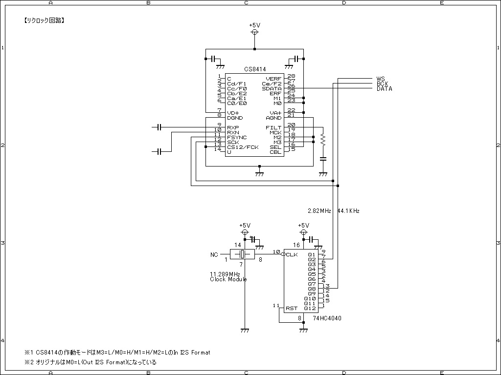
Setting aside my logical disdain for asynchronous re-clocking.
That second diagram depicts the CS8414 in audio port format 11. In this format, the CS8414 exhibits sample 'slip/repeat' behavior. The SCK signal is an input, while FSYNC and DATA are output signals synchronized to the SCK signal. This incurrs problems. Whenever SCK calls for an sample to be output, the next sequential sample may not yet be ready. Should the next sequential sample be called for too soon, the device will simply repeat the previous sample. Alternately, should the next sequential sample not be called for soon enough, the device will simply slip (skip over) that sample and output the following sample instead. Either way, the result is hard data errors. Oddly, the clock jitter via this approach could be low (using an synchronous counter chip, instead of that ripple counter) - outputting the wrong data but at the right time instants!
That first diagram depicts a simple re-clocking (re-registering) of the 3-wire digital signal stream. So, while worsening the jitter, it should not suffer hard data errors as that other method will - instead outputting the correct data but at the wrong time instants.
Last edited:
Regarding the first circuit: I can understand the use of a resynchronizing circuit, even if it is asynchronous, for a DAC with parallel data interface: glitches due to skew between the various bits might be worse than the extra jitter that the resynchronizer introduces (provided it is somehow assured that all parallel bits are always clocked in at the same clock cycle, which for a parallel interface requires a more complicated resynchronizer than just a bunch of double flip-flops).
What's the supposed advantage for a DAC with serial interface? Inside the DAC there must be an I2S interface that first puts all bits into a register and then copies all of them to a second register that drives the actual DAC. That is, the internal DAC logic determines the skew anyway.
What's the supposed advantage for a DAC with serial interface? Inside the DAC there must be an I2S interface that first puts all bits into a register and then copies all of them to a second register that drives the actual DAC. That is, the internal DAC logic determines the skew anyway.
What about using 74AC4040 instead of 74HC4040?
HC has a propagation delay from Qn to Qn+1 of 8ns typ
AC has a propagation delay from Qn to Qn+1 of 3ns max !😱
Faster counter (lower propagation delay) should be ALWAYS better in reclocking circuit, correct?🙄
Also do we really need TTL compatibility (HCT/ACT) or it is just ok HC/AC powered at 5V ?😎
HC has a propagation delay from Qn to Qn+1 of 8ns typ
AC has a propagation delay from Qn to Qn+1 of 3ns max !😱
Faster counter (lower propagation delay) should be ALWAYS better in reclocking circuit, correct?🙄
Also do we really need TTL compatibility (HCT/ACT) or it is just ok HC/AC powered at 5V ?😎
What about using 74AC4040 instead of 74HC4040?
HC has a propagation delay from Qn to Qn+1 of 8ns typ
AC has a propagation delay from Qn to Qn+1 of 3ns max !😱
Faster counter (lower propagation delay) should be ALWAYS better in reclocking circuit, correct?🙄
Also do we really need TTL compatibility (HCT/ACT) or it is just ok HC/AC powered at 5V ?😎
****addendum****
I have just read that 74AC are "noisy" logics....😱
Thus not preferable...
74hc or 74ac logic chips for digital audio ?
Did someone use 74ac4040 instead of 74hc4040 ?
Last edited:
- Status
- Not open for further replies.