Hi folks,
I have an Alto amp that works but has a slightly static/distorted sound out of one channel (right).
To clarify - About 2-3 years ago it didn't work (no right channel output) so we sent it to a repair centre and they 'fixed' it. I did a quick sound check on it at the time (got sound - must be ok) and it went into storage as we were using another system. The opportunity has come up to put it into service in a bedroom so I dusted it off and threw some speakers at it. It didn't 'sound' right and after a bit of trouble shooting, different speakers/cables etc I confirmed it is definitely the right channel that has the noise on it.
While not a qualified stereo repairman I do have some elec/radio knowledge from previous life in Air Force, so can muddle my way around a schematic etc.
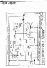
I found the schematics from another thread (thanks Ludwik!) and have gone through all the caps - they appear ok. The output posts seem secure. Nothing is jumping out at me.
I realise it's hard to faultfind over the internet but does anyone have an idea on what to look at next? I think the old repair for loss of channel was replacement of one or more power trannys (2N3055).
specific amp is a sweet little construction also given the simplicity of the design actually sounds pretty decent .
Add to the above that the quality of built eventhough simple is quite high and amplifiers like that don't fail often .
From upgrade aspect filter capacitor and output capacitors are undersized ( to my opinion) you could fit almost 15.000 mfd in power supply and at least 4700 in the outputs ( probably more ) bypass down under in the range of 2.2mfd for the power and 0.47 for the output will also improve the performance
places to look at for damage is
---selector switch faulty or dirty
---There has been reports that output relays fail quite often
---There has been some reports that some units had soldering issues ( left side from front view )
---There has been one case where the input transistors had a leak
---loose fuse holders , loose ground connections , poor soldering in the input buss ground area and or signal area
---If the unit has been working in a warm area replace all small capacitors ( no questions asked )
nothing else that i ve seen in the past
Kind regards
sakis
Hi Sakis,
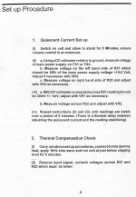
Many thanks for your reply. A bit of an update - I carried out the quiescent current setup as per the attached document. Left channel all good however with the right (problem channel) I don't get the 30mv voltage drop (step iii) across R22 and adjusting VR2 has no effect. I measure zero V drop.
R22 measures same resistance as left side (however only measured "in circuit") have not done any desoldering yet.
My circuit faultfinding skills are a little rusty and my test equipment is limited to a digital multimeter. Do you have any recommendations on the probable cause of no voltage drop across R22?
Remeber original fault is I get audio out of both channels but the right seems distorted in some way.
I am sure this fault is schoolboy stuff but I have been out of it for a long while😕
Thanks again
Steve


replace small capacitors all over the place may not cost more than 3 USD
Focus on the VBE multiplier area ( TR 3 area )
One good practice for fault finding when only a DVM is available is to measure voltage but not in reference to ground but in reference to the respective test point of the other channel
since power supply is common for both ch. at no signal no load conditions expect measuring the base of transistor X of left Chanel will have to measure just a few Milli volts when the other probe is placed to the base of the opposite transistor on the right Chanel
if you measure anything above a few milivolts this is teh area with the problem
Still though i have no answer from you if you inspected the capacitors or the soldering
repair is about following procedure
Bit of an update (not for the better unfortunately) I was probing around the board trying to fault find and inadvertently dragged the DMM probe across TR9's legs.
Fried a few transistors but they have been replaced. I still have the original fault of no current through TR13/R26 and TR5/R22 etc. No voltage drop across R22 and transistors cold to the touch.
They appear to be all biased correctly i.e. 0.6V across the base emitter junctions.
The zener and the 3 diodes are ok.
All transistors replaced.
Continuity's between components are good.
Heatsink sockets are good.
All caps have been replaced or swapped side to side.
I have probed all round the circuit and voltages are similar to left side apart from the no drop across R22/R26 etc.
I would greatly appreciate any guidance on what to do next.... I am going crazy here.
Thanks
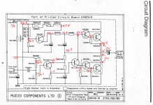
Can you power your amp up, and then take readings with your DVM, write them on to the circuit, and then post it back up again. We need the voltages at every major circuit node - so about 20 or so.
With this info, we can quickly help you to nail this thing.
With this info, we can quickly help you to nail this thing.
I am wondering if TR7 and TR5 are ok and not open circuit. You have about the right output voltage and I cannot see any major problems from the various readings. If TR5 was open, you would probably still get your output voltage because TR15 would pull current through R29. Reason I say this is you have 0V across R22 and across R26, so theres no Iq (or very little) flowing in the output devices.
Another option might be that R22 is open circuit.
I am a bit puzzled that you have ~1.2 V across the base emitter of TR15 - if ok, I assume it is a small signal darlington.
Another option might be that R22 is open circuit.
I am a bit puzzled that you have ~1.2 V across the base emitter of TR15 - if ok, I assume it is a small signal darlington.
Yes I (and others) thought that too but both transistors (in fact all) have been replaced and checked numerous times.I am wondering if TR7 and TR5 are ok and not open circuit. You have about the right output voltage and I cannot see any major problems from the various readings. If TR5 was open, you would probably still get your output voltage because TR15 would pull current through R29. Reason I say this is you have 0V across R22 and across R26, so theres no Iq (or very little) flowing in the output devices.
R22 (and R26) both removed from circuit and in fact swapped with left channel. They measure 0.4 ohm each. They are supposed to be 0.22 ohm (red red silver gold).Another option might be that R22 is open circuit.
TR15 has been replaced (twice), it is a BC556. Is 1.2V too high - what should I expect there?I am a bit puzzled that you have ~1.2 V across the base emitter of TR15 - if ok, I assume it is a small signal darlington.
Thanks Bonsai!
Well, if TR15 is a normal transistor, I think the base emitter voltage (looks like about 1.2V) is way too high - should be about 0.6V. Thats why I wondered if it was a darlington. What was the part number of the original one?
Your readings for R25 and R22 at 0.4 Ohm vs 0.22 Ohms - probably just your meter. You need a pretty decent DVM to read low Ohms accurately.
Last edited:
Can you describe the noise you are talking about in the 1st post?
If you feed a signal into the amp, do you get sound out of the faulty channel? how does it compare to the good channel?
If you feed a signal into the amp, do you get sound out of the faulty channel? how does it compare to the good channel?
Bit of an update, I ended up swapping out all transistors (again) either with new ones or side to side. When I changed the 2n3055 power trans side to side I noticed the voltage drop across output resistor R22 changed.
While I could adjust for the 30mA on the left side in original config when I changed them over I could only get 8-10mA and something similar on the the right (dud) side.
I thought I was on to something so I connected up a cd input and some speakers, expecting the fault to have changed sides. However left side still ran ok while the right had audio but was miniscule in volume and quite staticky (and doesn't adjust with volume knob).
While redoing the current setup for left trying to get the 30mA as per the schedule (which I can't get by the way - only about 8-10mA max) I noticed that moving the volume pot caused the right to jump in and out.
I investigated more and when I tweak the pot slightly by holding the shaft and applying a little down and left pressure I get clean audio and no hum!!
I tried cleaning it with a bit of isopropyl alcohol and recrimping up the little lugs (they were loose) but it still crackles (and shunts the audio to ground?).
I have a new one on order (its a 100k linear dual gang pot fyi), so hopefully tomorrow I will have this saga solved.
I'll keep you posted.
Thanks for your help - I would have given up long ago without it
There is peace and harmony again in the universe! haha
New volume pot fitted and also found a dry joint on the input cap C15.
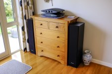
We now have clear crisp music in the bedroom and does it pump with the Polk RT12's!! I can't get the volume knob more than 1/8th(ish), certainly no more than 1/4, before it becomes TOO loud. Sounds really good too, no hum/crackle etc.
Thanks so much to everyone who helped, it's been a very frustrating experience (for me stumbling my way around the circuit) but also very rewarding.
I'm now keen to dive into some other sort of electronic project....

An externally hosted image should be here but it was not working when we last tested it.
New volume pot fitted and also found a dry joint on the input cap C15.
We now have clear crisp music in the bedroom and does it pump with the Polk RT12's!! I can't get the volume knob more than 1/8th(ish), certainly no more than 1/4, before it becomes TOO loud. Sounds really good too, no hum/crackle etc.
Thanks so much to everyone who helped, it's been a very frustrating experience (for me stumbling my way around the circuit) but also very rewarding.
I'm now keen to dive into some other sort of electronic project....

Good afternoon!
I'm looking for a replacement for my Audio Innovations Alto amplifier - the amp is defect and nobody seems to be able to fix it...
Anybody interested in selling me a good amplifier of this type? (chrome front...)
Fred
I'm looking for a replacement for my Audio Innovations Alto amplifier - the amp is defect and nobody seems to be able to fix it...
Anybody interested in selling me a good amplifier of this type? (chrome front...)
Fred
I'm looking for a replacement for my Audio Innovations Alto amplifier - the amp is defect and nobody seems to be able to fix it...
Anybody interested in selling me a good amplifier of this type? (chrome front...)
I'd be interested in buying your "dead" one, if you are not going to fix it
- Status
- Not open for further replies.
- Home
- Amplifiers
- Solid State
- Audio Innovations Alto amp - noise on one channel
