don't worry about modifying the HK polarization circuits, now I’m pretty good at it,
I have worked on a dozen A300s and A500s since my first message about the XAM mark IV (A300 from EJ Korvette) and I really like these two diagrams.
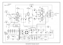
I enclose the diagram of the A500, you will understand the "balance bias pot"

to return to our sheep, the UL wiring of the audionote L1, can you explain to me what is against it?
Needless to say, I have UL opt😉
I am attaching the diagram of L1 that a guy has already modified, if you can tell me what you think about it.

I have worked on a dozen A300s and A500s since my first message about the XAM mark IV (A300 from EJ Korvette) and I really like these two diagrams.
I enclose the diagram of the A500, you will understand the "balance bias pot"
to return to our sheep, the UL wiring of the audionote L1, can you explain to me what is against it?
Needless to say, I have UL opt😉
I am attaching the diagram of L1 that a guy has already modified, if you can tell me what you think about it.
Attachments

a photo of a XAM mark IV (I don't have a photo of mine)

+ original schematic of the L1
.gif")
+ original schematic of the L1
Last edited:
so my first conclusion for those who would like to assemble this kit:
if you are looking for a "tubey" amp go your way, it's anything but that.
it is extremely fast, worn on the top of the spectrum and this includes
as a very good transistor amp AB.
Then, it has too much gain and is very very sensitive to the source, it brings out all the qualities but also all the faults of your source, for the best and also for the worst.
I tried a whole range of potentiometers (20k, 50k, 100k, 250k, 500k, 1Meg ohm), the best result (for me) was obtained with a buffer 6AK5 / ef95, but even without gain, I cannot exceed 10h on the volume.
It is therefore necessary to add a divider bridge to the input or pass the pentode as a triode on the ecf80, to be seen later ...
so if you have a pair of speakers that are a little too soft and dull, this is the amp you need to wake them up, however if you have fast and nervous speakers, go your way, it may be acidic.
I also specify that I do not have the original opt, but a pair of Supersonic which are certainly excellent opt but not those of origin AN.
the next step for me is to try the divider bridge (the simplest and the fastest)
then pass it in UL 40%
then the el84 in triode to see.
I like the "tubey" amplifiers so I have to dig a little
this one, otherwise it will quickly join my archives in a cupboard if
I can't "soften" it a bit
my opts are 10K, I tried the different secondary (3,6,9,15ohm)
Last edited:
Yes, I also found the gain of the AN L1 to be too high - had to use some low
value pot (I think 20K) to get any kind of control on the volume.
value pot (I think 20K) to get any kind of control on the volume.
huggygood,
Changing the gain:
1. For less gain, wire the input pentode in triode mode. But you certainly will have to re-adjust the bias and plate load, RL to get the voltage the same as it was before the mod. (for the concertina to be at the same voltage . . . important).
The dominant pole will no longer be at the right frequency, because the plate resistance of the triode wired input pentode is lower.
And . . .
Then, with less open loop gain (because of the triode wired input pentode), you should be able to increase the negative feedback. Reduce the feedback resistor, and increase the capacitance by the same ratio. for example, 1/3 the resistance, and 3x the capacitance.
That lowers the gain by 9.5 dB. Or 1/2 resistance and 2x capacitance, lowers the gain by 6 dB.
Or . . .
2. Change the output stage to triode wired, but that will reduce the maximum output power. But then, the lowered open loop gain will allow you to increase the negative feedback, like 1/2 resistance and 2x capacitance, 1/3 resistance and 3x capacitance, etc.
And that will allow you to keep the input pentode stage as is, and not have to muck with resetting the bias to so you can keep the concertina grid at the same voltage.
All my power amps use 50k audio taper input pots. that makes up for things like Miller Capacitance of triode inputs, more constant frequency pole of input filters, etc.
I did the below comments before I saw your post # 43:
Fundamentally the circuit looks good.
There is an error in the wiring of the transformer primary.
The plug says 241 Volts, but the primary halves are wired in parallel, that means it is set for 117V (not 241V).
Burnout. Bad!
Low Pass at input, 10k and 68 pF. 234kHz low pass, but is a lower frequency than than that, depending on where the volume control is set, and also the impedance of the signal source that is applied to the input connector.
No grid stopper between the low pass and pin 2 grid.
So the input grid is tied to ground through 68 pF.
Series RC dominant pole at triode grid pin 9.
150k RL and 5.6k and 100 pF 10.2 kHz dominant pole frequency.
No grid stopper between dominant pole network and pin 9.
The stability of the amp is dependent on the output transformer having the correct parameters.
Some transformers that are used as a substitute may, or may not, be stable with the negative feedback parts values. Some adjustment may be needed.
The amp is in UL mode (not Pentode mode), and UL may be a little more forgiving of transformer substitutes, given the global negative feedback parts values.
Part of that depends on the leakage reactance from the full plate winding to the portion of that winding that is to the screen; and part of that depends on the leakage reactance from the plate windings to the output windings.
I am not a fan of the capacitors that are across the B+ secondary.
May be needed, but I suspect not.
Are they there for noise suppression?
If instead they are there to deal with super bad line transients, they may not survive a transient.
A multi outlet power strip with surge suppressor is better for that function.
A power strip also saves switches wearing out on all the equipment that is plugged into it.
Just use the power strip switch as the master switch. It is easier to replace the power strip than to replace a switch on an amplifier.
Your only bleeder resistors are the 270k and 47k voltage divider that elevates the filament voltages. You have 332uF total capacitance in the B+ filters.
270k + 47k = 317k
317k x 332uF = 105 Second time constant, very long.
The discharge of the caps when the tubes are still warm will help, but it will be several minutes until the caps are discharged far enough to make it safe to get into the amp after power down.
An additional bleeder resistor may be in order.
Is the amp built on a circuit board, or is the wiring point to point?
Are you using the exact original model of the output transformer?
Last edited:
I listened to this amp for a long time yesterday and it is clear that this amp needs to be overhauled.
I tried it with several sources and several pairs of speakers, it is really very demanding and seems to have been designed to work with a source and a pair of very specific speakers, which I do not like at all.
fort of this observation and, it must be said, a little annoyed, I came out of its box (I am in transit between two houses) my A300 to see, and the verdict fell in less than 30min, in the state current, I do not like the L1, it reminds me of a Ferrarie while me what I like is a Buick riviera and even, in this case for the A300, an Oldsmobile 88 52.
So since I don't like it like that, I'm going to try what you offer.
My opt are not those of origin but are very very good,
I also have others that I can try but for now, I want to see if there is a way to make it sound otherwise by starting to decrease its gain, wire in triode the el84 and maybe the ecf80 by the following .
EDIT: it's a PCB
I stopped using PCBs in my tube amps when I tore up my Dyna Stereo 70. The PCB went into the trash (but not before I tried triode wired EL34s, and tried Single Ended EL34s with air gap modified A470 output transformers).
I found out quickly, that modifying a PCB is not even worth my time and effort (personal choice).
After removing the PCB, the Dyna has been a test bed for many different amplifier topologies and circuits, mono-block, stereo, SE, Push Pull, DHT, indirect heating, Solid State rectified, Cap input B+, Choke input B+, Interstage Transformer coupling, RC coupling, Auto-Transformer Phase inverting, LTP current source phase inverter, Serial Phase inverter, and combinations of all the above.
did I cover all the versions I built on that test bed, probably not.
Oh . . . and I am planning another circuit on that chassis, as soon as I get the time.
The worst feature of the Dyna Stereo 70 is the Steel Chassis.
1. Conducts power transformer and B+ choke magnetic interference to the output transformer(s), and when present, the interstage transformers.
2. The next worst feature of the steel chassis is drilling it for different parts.
I got more use out of that chassis than anybody ever was paid on eBay for a
pristine Dyna Stereo 70 (You be the judge).
How about using a current sink connected to the parallel cathodes of a dual triode phase splitter/driver to the EL84s in UL mode.
Then bring the negative feed back from the output transformer 8 Ohm tap (or appropriate loaded tap) to the un-driven grid of the phase splitter.
Less open loop gain, should work with moderate negative feedback, and have moderate output power and moderate distortion.
Just another idea.
May require some adjustment of the negative feedback parts.
After researching and ruminating the thing in all directions, I ended up opting for the "REV F" of the diagram and for once, I'm really not disappointed.
It is no longer the same amp, it just keeps its "fast" side but is no longer tiring like the previous version.
I listened to it for two days and I never get tired of it, however it is still too sensitive, much too sensitive.
I have not yet passed the pentode of the ECF80 in triode, I will try that later, I must determine the best connection compared to the diagram (G2 on anode or cathode)
I attach the diagram for those who also work on it.

After researching and ruminating the thing in all directions, I ended up opting for the "REV F" of the diagram and for once, I'm really not disappointed.
It is no longer the same amp, it just keeps its "fast" side but is no longer tiring like the previous version.
I listened to it for two days and I never get tired of it, however it is still too sensitive, much too sensitive.
I have not yet passed the pentode of the ECF80 in triode, I will try that later, I must determine the best connection compared to the diagram (G2 on anode or cathode)
I attach the diagram for those who also work on it.
View attachment 840334
I'm happy that someone with much more experience in this field than I, has improved this circuit. I'll design and construct new PCB to fit this circuit in original Chifi housing.
Thanks,
Jim
Attachments


I built a L1 clone for a friend of mine - it sounds very good. Having everything
on one (large) PCB has it's advantages, but I think what Jim (oemcar) is doing
makes it much easier in terms of enclosure design.
Look forward to the new board.
Finally finished this retrofit PCB-
Haven't put circuit through final check yet. Ended up using the Rev F for layout except the power supply, where i decided to keep the ChiFi PI network (But changed out the 75ohm res for 1H coil) remote located off board to save space. 1, 2, & 3W resistors are mounted stand up to save space also.
Original board measures 3.2' x 7.2". This one 7.5" x 3.5", but will fit in chassis. Added a parallel LC to the signal input to enhance the lo's and hi's- mod done to the orig Chifi design that my ears liked. Also added UL option for components when upgrading transformers later (probably Dynakit Z565's).
6U8A traces are mostly .032". 6BQ5 traces are mostly .048". Filament traces are .064". Tried to maintain .100" space between traces. Rev F schematic is posted also so if somebody sees a design issue with above noted changes, let me know.
Thanks,
Jim
Attachments

Last edited:
Just discovered this topic.
Just wondering, I recently picked up an old Audio Innovations 200MK2 Power amp.
Thing is, the pcb in this amp is totally gone.
lots of corrosion, loose solder joint, beyond repair.
And its out of my league to convert the amp into a hard wired version.
But can I use the OPT's and Power Transformer building the clone L1 EL84 ??.
Any input is welcome.
You would need to be extremely lucky with the placement of the tubes, or be able to adapt an existing board spec so that boards could be produced that fit.
After researching and ruminating the thing in all directions, I ended up opting for the "REV F" of the diagram and for once, I'm really not disappointed.
It is no longer the same amp, it just keeps its "fast" side but is no longer tiring like the previous version.
I listened to it for two days and I never get tired of it, however it is still too sensitive, much too sensitive.
I have not yet passed the pentode of the ECF80 in triode, I will try that later, I must determine the best connection compared to the diagram (G2 on anode or cathode)
I attach the diagram for those who also work on it.
View attachment 840334
The text is not always clear, not finding a input transformer under "ank-li-84", additionally, see 117 volts (assume mains) and 230 volts (and B+), are these the requirements? How many amps? No common terminal, correct?
Additionally, see 12,6 volts, is this the heater voltage? How many amps?
300 volt plate voltage?
I think reading the other numbers fine, if later when looking up in the catalogue can come back and inquire again.
Thanks in advance! 🙂
For those folks also needing tube specifications:
https://frank.pocnet.net/sheets/019/e/ECF80.pdf
https://frank.pocnet.net/sheets/019/e/EL84.pdf
In this case, minimum heater amps is = (2*0,43amps)+(2*0,76amps)=2,38amps.
The trouble is the differences between the diagrams, one has voltages labeled and one does not. The one labeled has ECF80 plate voltages of 89VDC and 198VDC, neither the 170VDC specification. So which is correct? If the former, how many milliamps? Again, same for the EL-84, the biggest concern is the table of 325VDC, exceeding the specification of 300VDC. Which is correct and if the former, how do we adjust so as to get to the 300VDC and therefore known amperage?
Hi @Adriel
"The trouble is the differences between the diagrams, one has voltages labeled and one does not. The one labeled has ECF80 plate voltages of 89VDC and 198VDC, neither the 170VDC specification. So which is correct?"
Both are correct 🙂
The datasheet is showing you a "typical" use, as a high frequency mixer. The ECF80 is a television tube, not originally designed for audio, but, as luck would have it, many TV tubes are pretty good when used for audio. Tubes also do not have just one working voltage/current/bias. Is a range, as you can see in the datasheet curves, therefore you choose a working point depending on what you need.
The triode section is used as a split-load (also called "Concertina" and other names) phase inverter for the push-pull stage. The pentode is used purely for voltage amplification. But the pentode's plate is DC coupled to the triode grid, and that means you need to keep it low to be able to bias the phase-splitter in a way that you have symmetrical output signals and clipping. That forces the pentode plate voltage to be relatively low. There is no issue with that.
About the EL84, you have 325DC plate, and 10V at the cathodes, 315V across the tube. That's a bit higher than the specs of the original EL84, but it is pretty close, I would not bother much about it. Moreover, some of modern production EL84s are based on a Soviet 6P14P design, that has higher anode voltage rating.
I hope I got it right 🙂
Hi @jcalvarez ,
I am actually reading the section above titled "Operating Characteristics."
Interesting.
Two "problems": cart doesn't go above 300VDC and I don't know what I need as not the original designer.
V1-P to V1-T via terminals 3, 7, and 9?
Not planning to change the design, simply obtain the transformer specification as have not heard back from anyone on it (look how long I have waited for someone to model the speakers, clearly if I need something advanced, have to figure it out, folks have lives to live).
I have been told guitar amplifiers run the tubes at 150 percent design voltage.
Where do you get the 315VDC figure from?
What about the other odd voltages?
The datasheet is showing you a "typical" use, as a high frequency mixer.
I am actually reading the section above titled "Operating Characteristics."
The ECF80 is a television tube, not originally designed for audio, but, as luck would have it, many TV tubes are pretty good when used for audio.
Interesting.
Tubes also do not have just one working voltage/current/bias. Is a range, as you can see in the datasheet curves, therefore you choose a working point depending on what you need.
Two "problems": cart doesn't go above 300VDC and I don't know what I need as not the original designer.
The triode section is used as a split-load (also called "Concertina" and other names) phase inverter for the push-pull stage. The pentode is used purely for voltage amplification. But the pentode's plate is DC coupled to the triode grid, and that means you need to keep it low to be able to bias the phase-splitter in a way that you have symmetrical output signals and clipping. That forces the pentode plate voltage to be relatively low. There is no issue with that.
V1-P to V1-T via terminals 3, 7, and 9?
Not planning to change the design, simply obtain the transformer specification as have not heard back from anyone on it (look how long I have waited for someone to model the speakers, clearly if I need something advanced, have to figure it out, folks have lives to live).
About the EL84, you have 325DC plate, and 10V at the cathodes, 315V across the tube. That's a bit higher than the specs of the original EL84, but it is pretty close, I would not bother much about it. Moreover, some of modern production EL84s are based on a Soviet 6P14P design, that has higher anode voltage rating.
I have been told guitar amplifiers run the tubes at 150 percent design voltage.
Where do you get the 315VDC figure from?
What about the other odd voltages?
Doing some research, find this information:
https://www.digchip.com/datasheets/parts/datasheet/1019/ECF80-pdf.php
Provides pentode of 10mA/0,010A and triode of 14mA/0,014A with a maximum for both of 0,014A.
"If your plate voltage is 330VDC it it highly likely that your amp is a class AB design and the ideal safe plate current would be between 19mA and 26mA."
EL84 "Maximum Cathode Current, Ik 65 mA[0,065A]"
Therefore, for the sound portion of the tubes: (2*0,014A)+(2*0,065A)=0,158A.
Giving a transformer with a 110VAC primary with a secondary of 6,3 volt, 2,4A minimum and a transformer of 110VAC primary with a secondary of 2x115VAC at 0,2A, or 46VA minimum.
Hopefully this is right, really sleepy for some reason.
Onto the BOM.
The maximum plate voltage in a datasheet refers to plate-to-cathode voltage. The schematic shows around 10V voltage in the EL84 cathode, therefore the plate voltage is 325-10=315.Hi @jcalvarez ,
I am actually reading the section above titled "Operating Characteristics."
Interesting.
Two "problems": cart doesn't go above 300VDC and I don't know what I need as not the original designer.
V1-P to V1-T via terminals 3, 7, and 9?
Not planning to change the design, simply obtain the transformer specification as have not heard back from anyone on it (look how long I have waited for someone to model the speakers, clearly if I need something advanced, have to figure it out, folks have lives to live).
I have been told guitar amplifiers run the tubes at 150 percent design voltage.
Where do you get the 315VDC figure from?
What about the other odd voltages?
Which other voltages are odd?
The maximum plate voltage in a datasheet refers to plate-to-cathode voltage. The schematic shows around 10V voltage in the EL84 cathode, therefore the plate voltage is 325-10=315.
Okay, appreciate the explanation.
The charts only go to 300VDC and the transformer is not specified, so how are the amperages calculated? Seems the plate voltage has to be dropped in order to specify a transformer, with the additional benefit of longer life? Sure wish hadn't offended oemcar, save you having to deal with my plethora of questions, ah the joy of Autism.
Which other voltages are odd?
89VDC at six, 0,85VAC at seven, 198VDC at one, and 92VDC at eight.
- Home
- Amplifiers
- Tubes / Valves
- Audio Note Kits L1 Build...