Hey DIY colleagues,
I own two Auralic Aries G1 and want to improve/change the existing power supply PCB with a new self developed one. I searched all the latest posts here in the forum and decided to try the LT3045/L3042 NPN version. But to be honest I just have several degrees in economics but none in electronics 😊 But after a few other power supply projects in KiCad and want to reach the next level... but learning can only be achieved when somebody tells you how it works in reality.
I hope you can help me regarding my project or perhaps you are also interested in this board for your Aries G1. Ex factory: Two LM317 regulators and standard brigde rectifiers (without snubber resistors). Have a look here: https://positive-feedback.com/wp-content/uploads/2020/09/img-4-auralic-streamer-review.jpg
What is the plan:
Measured power consumption of the Aries G1:
My questions are based on the attached circuit schematic:
Best regards
Andy
I own two Auralic Aries G1 and want to improve/change the existing power supply PCB with a new self developed one. I searched all the latest posts here in the forum and decided to try the LT3045/L3042 NPN version. But to be honest I just have several degrees in economics but none in electronics 😊 But after a few other power supply projects in KiCad and want to reach the next level... but learning can only be achieved when somebody tells you how it works in reality.
I hope you can help me regarding my project or perhaps you are also interested in this board for your Aries G1. Ex factory: Two LM317 regulators and standard brigde rectifiers (without snubber resistors). Have a look here: https://positive-feedback.com/wp-content/uploads/2020/09/img-4-auralic-streamer-review.jpg
What is the plan:
- 2x Talema transformers (7V and 15V)
- Epcos chokes
- LT4320 active rectifiers
- a bank of Panasonic FR 12mOhm capacitors (35V 2200uF)
- 15V System Rail: LT3042 with NPN (for the 15V system (Display, XMOS controller,….))
- 5,6V clock Rail: two parallel LT3045 for the 5,6V clock rail.
Measured power consumption of the Aries G1:
- System Rail: 16,8V @0,4A . But I tried it with 15V @0,5A ZeroZone Supply and it also works flawless.
- Clock Rail: 5,6V @0,3A. Should stay at 5,6V
My questions are based on the attached circuit schematic:
- 15V System Rail: I want to reduce the heat dissipation and use the already drilled mounting holes for the TO-220 LM317 regulators. For the 15V system rail I used NPN Transistors as shown in the LT3042 tutorial from Analog (Increasing Output Current of the Ultralow Noise, Ultrahigh PSRR LT3042 200mA Linear Regulator | Analog Devices) . Question: Should I use this NPN based circuit or switch to a parallel LT3045 based solution? Parallel-version: How much heat will be produced on the LT3045 chips? Perhaps somebody can help me to calculate this? Do I need extra heatsinks?
- 15V System Rail: I tried to implement CRCRC resistors after the LT4320. Is my calculation correct? If not, how can I calculate the correct CRCRC resistors? You can find my calculation way in the circuit drawings.
- 5,6V Clock Rail: Same CRCRC resistor questions here.
- 15V and 5,6V Rail: I tried my very best in copying and adopting the LT3042/45 schematics I found here and on the Analog site. But can you please check if I made some faults choosing the correct resistor values?
- Output capacitors: Analog only recommend a small 10uF (or a little bit more) on the output. But I found several LT3045 implemtations with a lot more uF… What would you recommend?
- LT3042/45 sense line configuration: Some implementations have a third contact for the sense line (Plus, Ground, Sense) and some implementations already combined Plus and Sense in just one output. What would you recommend? (My opinion: Seperate Plus and Sense and combine the two Plus/Sense cables in one (Y-Version) – Am i right?).
- MOST important DIY Audio question: Can you recommend any improvements I should consider 😊
Best regards
Andy
Attachments
Hi since you asked me by PM I will shoot. Have to go so a short post.
1. I would use a Talema 2 x 7V transformer for the 15V rail. I even use 12V transformers with ULDO and have steady 15V regulated output but then it is tight and it depends on the transformer in question. Like you I want to keep heat to a minimum certainly when using LT3042/3045. Use much copper so a large area to keep them cool.
2. I would use CLC and RF circuit like approach.
3. Same as 2.
4. Will ook into that later.
5. The circuits don't need much more than 100 µF in total but it depends on what types you use. Please don't use polymer types at that spot. 10 µF X7R is the absolute minimum...
6. Separate Sense and + but tied together at load.
7. Busy with that. For instance the 15V I would overdimension slightly and use 2 x LT3045 in parallel. Better performance than with a pass transistor. My current PSU uses 3 in parallel.
In my personal tests and extreme PSU building efforts the LT3045 in parallel is better than LT3045 with pass transistors. My Aries Mini however loves a single TPS7A4700 a little more despite its on paper less good properties. This is the IC that Auralic uses in their upgrade linear PSU's. If you design in TO220 format things will also work out (or maybe you can try both and add pads for a TO220 style TPS7A4700 regulator).
Last edited:
Spelbreker! 🙂 Yes we know there is a Hoerwege PSU but where is the fun in that? 99% of what is offered here on diyaudio.com can be bought ready made 🙂
Schlaudi, I think you also want Power Good Feedback and fast startup on U4 and U5. I would advise to use a 6V transformer for the 5.6V PSU instead of the 7V type. You could even try out a 5V type but it will then depend on make/type and it can be tight. In my experiments it works perfect for 5V output, certainly when using LT4320 and using large value capacitors (in my case 10,000 µF). As long as there is a margin for the PSU to work correctly both at low and high mains voltage at maximum load I think it is OK. It is not how I got it taught though 😀 but then no one cared about heat and power consumption.
Last edited:
It is a complete new design. I don't think there is a schematic of the Hoerwege version publicly available (and copying is too easy). It seems Schlaudi wants to get the best out of it so lowest possible energy loss and best possible noise numbers/good RF suppression.
Last edited:
I bought an hoer wege PS and not satisfied with it.. its dull sounding. Instruments are sounding fuzzy, i could pinpoint before.
The original LM317 PS with just only 2 caps per voltage rail is sounding more dynamic.
Had anyone made /finished this LM3042/3045 design ?
The original LM317 PS with just only 2 caps per voltage rail is sounding more dynamic.
Had anyone made /finished this LM3042/3045 design ?
When the Hoerwege is brand new it will take some time to settle. Always a subject for heated debate 😉 If it performs worse than the original then something might be wrong. Did you measure?
Schlaudi sent me a message recently and I remember that he picked up this design again.
Schlaudi sent me a message recently and I remember that he picked up this design again.
Nice, i hope it will be better then the HW unit.When the Hoerwege is brand new it will take some time to settle. Always a subject for heated debate 😉 If it performs worse than the original then something might be wrong. Did you measure?
Schlaudi sent me a message recently and I remember that he picked up this design again.
The HW plays for Some days but i dont trust it to get hugely better then this.
Yes measured voltages.
Last edited:
Hi JP,
Hi tubee,
yes, I hope I will find some time within the next weeks to finalize the design and post the solution before before ordering the first PCBs. I decided to use the LT3042 / NPN TO-220 instead a dual LT3045 configuration. So it's a plug and play solution and you just can swap the existing PCB with my version. The heat dissipation will be done via the existing aluminium plate and the same TO-220 mouting holes. But it will take some more time...
To be honest, I read a lot about the LT3045 and it seems that there could be a lot of frequency problems (Mhz-GhZ Sector) if the PCB-design isn't perfect. I don't have the equipment and knowledge to measure with a spectrum analyser in this regions.
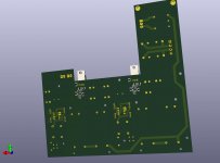
Attached you will find some 3D animation (with some missing or wrong 3D objects 🙂 )
Hi tubee,
yes, I hope I will find some time within the next weeks to finalize the design and post the solution before before ordering the first PCBs. I decided to use the LT3042 / NPN TO-220 instead a dual LT3045 configuration. So it's a plug and play solution and you just can swap the existing PCB with my version. The heat dissipation will be done via the existing aluminium plate and the same TO-220 mouting holes. But it will take some more time...
To be honest, I read a lot about the LT3045 and it seems that there could be a lot of frequency problems (Mhz-GhZ Sector) if the PCB-design isn't perfect. I don't have the equipment and knowledge to measure with a spectrum analyser in this regions.
Attached you will find some 3D animation (with some missing or wrong 3D objects 🙂 )
Attachments

Nice design!Hi JP,
Hi tubee,
yes, I hope I will find some time within the next weeks to finalize the design and post the solution before before ordering the first PCBs. I decided to use the LT3042 / NPN TO-220 instead a dual LT3045 configuration. So it's a plug and play solution and you just can swap the existing PCB with my version. The heat dissipation will be done via the existing aluminium plate and the same TO-220 mouting holes. But it will take some more time...
To be honest, I read a lot about the LT3045 and it seems that there could be a lot of frequency problems (Mhz-GhZ Sector) if the PCB-design isn't perfect. I don't have the equipment and knowledge to measure with a spectrum analyser in this regions.
Attached you will find some 3D animation (with some missing or wrong 3D objects 🙂 )
My humble thoughts:
1 shaffner inlet filter is sufficiënt.
I hope the LTO to NPN design will not sound dull. My suggestion choose a fast transistor for that purpose. Or parallel chips
In the HW unit a 3 transistor regulator is used, the filosophy is to enhance current delivery when needed, but the current is mostly continous and only sub 500 mA so a huge regulator can in my opninion better changed for a ‘fast ‘ but smaller regulator instead. That is also why shunt regulators are often a better choice in audio.
I also suspect the big electrolytic cap bank for the muffled sound.
Anyway, If you have the design tested i would like to try One also in time 😃
Last edited:
I am also interested in the final result of your PCB/ print design with accompanying components.
As I understand the original PCB has no options of upgrading with better components??
As I understand the original PCB has no options of upgrading with better components??
Yes it can somehow be upgraded, but limited. After the transformers a simple smd rectifier is used not simple to substitute to hexfred or better or something. Before regulator chip LM317 a 2200uf 35 v cap, Some parts around regulator an a last smd lytic is used. The 2200 uF (through hole) can be modified and that would be all i guess. Or solder Some low esr caps extra on underside board. Modifiing rectifier can Maybe when a riser board or something is madeAs I understand the original PCB has no options of upgrading with better components??
What are you trying to say with:Yes it can somehow be upgraded, but limited. After the transformers a simple smd rectifier is used not simple to substitute to hexfred or better or something. Before regulator chip LM317 a 2200uf 35 v cap, Some parts around regulator an a last smd lytic is used. The 2200 uF (through hole) can be modified and that would be all i guess. Or solder Some low esr caps extra on underside board. Modifiing rectifier can Maybe when a riser board or something is made
???a simple smd rectifier is used not simple to substitute to hexfred or better or something.

I also have plans to make project based on some ULN regulators. I have question, did you measure power consumption and ripple on stock PS during DSD (playback or resampling) using USB DAC (most of them are feeded from USB 5V PS) and connected USB pendrive simultaneously? I think that numbers will change dramatically and could boil little LT regulators 🤔 Maybe Super Regulator will be the best solution here.
- Home
- Amplifiers
- Power Supplies
- Auralic Aries G1 Power Supply PCB with LT3042/LT3045