Jox knows what he is speaking about. He has had to make them work. If he can supply a circuit it will work. I believe it will be pretty simple.
I can't help with the Behrenger cold but if you post the connector pinout we can give advise on a suitable supply.
-Demian
I can't help with the Behrenger cold but if you post the connector pinout we can give advise on a suitable supply.
-Demian
If it's a pre-polarized mic capsule, you'll need a 5 mA current source with a voltage of 24V with nothing connected to it.
If your pre-amplifier has a BNC connector, it's a DeltaTron supply you need (which is what I described above).
Your pre-amp output should bias itself to half the supply voltage (roughly), with the signal as AC "on top" of the DC. That's why you need a capacitor.
However, remember that the pre-amp is basically an impedance lowering device, with unity gain. You'll need to make the gain stage yourself, but a decent op-amp will do the trick.
Jennice
signal conditioner
I've not used a signal conditioner such as the one on ebay you recommended.
http://cgi.ebay.com/ws/eBayISAPI.dll?ViewItem&rd=1&item=3843628096&ssPageName=STRK:MEWA:IT
Its going in an hour. Based on what we know, will it help the noise problem? Will it provide the right current, and some gain? thanks. Ted.
It will work. It should fix the hum problem if the problem is from the interface. I have the manual and can help with any details. If it doesn't work for you I'll buy it from you (so I have a pair and can look at vibration propagating through a speaker cabinet).
-Demian
-Demian
Qu
Yeah. I use spectra plus - and do a lot of things like that - esp for tweeking crossovers. Several years ago I used contact mics to measure propegation of sound through wood for a guitar maker with some very interesting results. (Good transmission through the wood leads to phase cancellation - dead spots - in the guitar. ). Alas, leo fender made guitars sound better by making them, in some respects, worse.
I would induce white noise into the wood via a headphone playing white noise, and then record the results with the contact mic in different places. I developed tables for engineering music tracks such that we can make any guitar sound like almost any other guitar using eq. silly, I know - but that's why I want this mic to work. ted.
TheoM,
You'll probably want to make your mic.-supply as a current source with 27 - 28 Vdc as voltage, and 5 - 10 mA constant current.
The mic-preamp you have (if it's a tube thingy with the mic capsule in one end and the BNC in the other end), is not designed to have gain.
Consider it to be an impedance changing circuit. Some megaohms to the capsule, some hundred ohms to the BNC side.
However, it is very critical that you filter out ripple in this supply. Any ripple will have severe influence on the output signal, especially since any existing ripple is introduced before a gain stage. You might want to consider using 3 x 9V batteries in series to feed the current source. Current demand isn't high, so you'll have quite a few hours of operation from such 3 cells.
As for the gain stage, there's no rocket science in it - just use low noise op-amps.
Jennice
Which mic is it? I used to use a B&K 4133 mic for measurement work, and this was a true unpolarised capacitor mic that needed a 200V polarisation voltage. (From a little PSU that used 'D' cells).
If yours only needs a standard phantom feed then this is quite easy. Have a look on the web for the application notes on the SSM2017 (or the replacement SSM2019) from Analog Devices and this shows the schematic of a pre-amp with phantom feed to the mic.
If yours needs a higher voltage it's quite easy to arrange.
Hello
I have myself few B&K 4145 mics capsules, unpolarised capacitor mic that needed a 200V polarisation voltage, but I don't have a power supply/preamps.
Would you have or know any schematics of transistors power supply/preamps for my 4145 ?
Thank
Bye
Gaetan
Normally the mic capsule screws on to a cylindrical pre-amp body. This pre-amp is powered from the dc supply, while providing both the dc feed to the capsule (through a resistor chain of hundreds of Megohms) and crucially, a very high input impedance buffer stage for the capacitor microphone. The buffer stage is not easy to design or make yourself, and the pre-amps (from B&K or other manufacturers) are not cheap.
Getting the 200V dc is simple, and a low-cost flyback supply is easy enough to design, but you still need to design the buffer amp with an input impedance of 1G Ohm or so. The mic capsule is only about 20pF, so you can understand how high the Z(in) has to be to get a useful LF response.
(One reason why vacuum tube capacitor mic pre-amps continued in use for so long).
Normally the mic capsule screws on to a cylindrical pre-amp body. This pre-amp is powered from the dc supply, while providing both the dc feed to the capsule (through a resistor chain of hundreds of Megohms) and crucially, a very high input impedance buffer stage for the capacitor microphone. The buffer stage is not easy to design or make yourself, and the pre-amps (from B&K or other manufacturers) are not cheap.
Getting the 200V dc is simple, and a low-cost flyback supply is easy enough to design, but you still need to design the buffer amp with an input impedance of 1G Ohm or so. The mic capsule is only about 20pF, so you can understand how high the Z(in) has to be to get a useful LF response.
(One reason why vacuum tube capacitor mic pre-amps continued in use for so long).
Hello
It would need a fet input buffer or an fet input opamp buffer.
I've found this circuit on the web, just need to change voltages, what do you think of it, does it need any improvements ?
Thank
Bye
Gaetan
Attachments
I'm not sure it will work for the B&K mikes. The cap leakage needs to be really low. You need a biasing method for the transistor or it will probably shut itself off. The real ones use things like teflon standoffs for the critical connections and the input cap is much smaller.
If you are interested I'll scan the HP circuit and post it. Its the simplest and one of the best I have tried. You will need some 1G resistors or similar.
If you are interested I'll scan the HP circuit and post it. Its the simplest and one of the best I have tried. You will need some 1G resistors or similar.
I'm not sure it will work for the B&K mikes. The cap leakage needs to be really low. You need a biasing method for the transistor or it will probably shut itself off. The real ones use things like teflon standoffs for the critical connections and the input cap is much smaller.
If you are interested I'll scan the HP circuit and post it. Its the simplest and one of the best I have tried. You will need some 1G resistors or similar.
Hello
Yes, I'm interest in your HP circuit.
Thank you
Bye
Gaetan

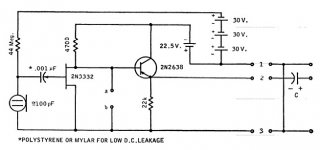
Here is the circuit for the HP15118A preamp.
Hello
Is there any special requirements for some parts ?
Which transistors numbers would you suggest for Q1 and Q2 ?
For CR2 and CR3, any fast diodes with the right voltage can do ?
Thank a lot
Bye
Gaetan
HP Part numbers:
Q1 1855-0020
Q2 1854-0307
CR1 51.1V 5% Zener
CR2 1901-0376 35V working 2 pF at 0V low leakage. (Not a fast switching device, its for protection of the transistors.)
1GOhm resistors are intrinsically special.
The caps are ceramic for low leakage.
The mechanicals are more challenging than the electronics.
There are HP cross references on the web somewhere for the transistors.
HP Part numbers:
CR2 1901-0376 35V working 2 pF at 0V low leakage. (Not a fast switching device, its for protection of the transistors.)
There are HP cross references on the web somewhere for the transistors.
Fast switching and low leakage are usually mutually exclusive. Something like a 1/2 a BAV191 should work.
Hi Demian,
Thank you for that diagram.
Absolutely! The mechanical stuff is what determines how well it works. Using Teflon standoffs is very common in instrumentation. Blocking any air currents is another thing to watch for. So many issues to think about.
Hi Scott,
I have read that a signal J-Fet also makes a good low leakage diode. I can't place where I read that at the moment. Also, glass diodes need to be shielded from all light. The BAV191 is surface mount, isn't it? (= light not an issue).
-Chris
If I can find it I have the schematics for the early B&K tube preamps as well as the more recent ones. I'll post them when I find them. It is interesting to see the different approaches.
Hello guy's
The Teflon standoffs are for the pcboard ?
Here is the HP cross references that I've found.
Q1 1855-0020 = SFE793
Q2 1854-0307 = BCY 57/LV2345
CR1 51.1V 5% Zener
CR2 1901-0376 = 1N359
Thank
Bye
Gaetan
The Teflon standoffs are for the pcboard ?
Here is the HP cross references that I've found.
Q1 1855-0020 = SFE793
Q2 1854-0307 = BCY 57/LV2345
CR1 51.1V 5% Zener
CR2 1901-0376 = 1N359
Thank
Bye
Gaetan
Good work on the cross references. Perhaps you can find datasheets on those parts?
The teflon standoffs are to reduce stay leakage that a PCB may have. The critical connections are the ones at the far ends of the 1 GOhm resistors. The impedances are very high.
If I get a chance I'll take a picture of the insides of a preamp to show the construction.
The teflon standoffs are to reduce stay leakage that a PCB may have. The critical connections are the ones at the far ends of the 1 GOhm resistors. The impedances are very high.
If I get a chance I'll take a picture of the insides of a preamp to show the construction.
Hi Demian,
Thank you for that diagram.
Absolutely! The mechanical stuff is what determines how well it works. Using Teflon standoffs is very common in instrumentation. Blocking any air currents is another thing to watch for. So many issues to think about.
Hi Scott,
I have read that a signal J-Fet also makes a good low leakage diode. I can't place where I read that at the moment. Also, glass diodes need to be shielded from all light. The BAV191 is surface mount, isn't it? (= light not an issue).
-Chris
Yes cut the drain off of a 2N4418 and use the gate to source, typically 20fA leakage. BTW part 2 of my Linear Audio article will cover a lot of similar stuff. Including eliminating the G Ohm resistors in some circuits and using just these diodes, as well as an interesting way to generate the bias without an oscillator or any switching at all.
You can stuff a tiny piece of #24 teflon wire wrap wire into a slightly undersized hole and it makes a good stand-in for the stand-off.
Last edited:
- Home
- Amplifiers
- Power Supplies
- B&K microphone power supply - help needed