Hi everyone,
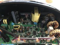
Nice to see this thread, I was just "gifted" a couple of Rotel RMB-1512 power amplifiers using 4 x IcePower 200ASC Rev J modules and 8 x IcePower 200AC Rev E modules each.
A bunch of channels are not working, some with the red fault LED turned off and some not, others have a very very low ouput signal and some are working... I have max 6 channels working on the 24 that the 2 Rotels should be able to output.
I'll try to take everything apart later in the week and to figure out how I can bring those channels back from their slumber. The informations posted here are invaluable !
I have a project to wire a friends workshop using a dozen PA speakers (old Bouyer ball speakers) and those amps would be perfect") Wish me luck !
Wish me luck !
Nice to see this thread, I was just "gifted" a couple of Rotel RMB-1512 power amplifiers using 4 x IcePower 200ASC Rev J modules and 8 x IcePower 200AC Rev E modules each.
A bunch of channels are not working, some with the red fault LED turned off and some not, others have a very very low ouput signal and some are working... I have max 6 channels working on the 24 that the 2 Rotels should be able to output.
I'll try to take everything apart later in the week and to figure out how I can bring those channels back from their slumber. The informations posted here are invaluable !
I have a project to wire a friends workshop using a dozen PA speakers (old Bouyer ball speakers) and those amps would be perfect
Wish me luck !That is pretty bad indeed, obviously there is more faulty.
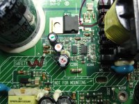
I wonder what might have caused the scorch mark close to "T200".
This is the area of insulation barrier under the main power transformer.
What did burn there? Perhaps something between xformer and pcb top side?
Could you check the secondary rectifier - not seen on this foto?
I wonder what might have caused the scorch mark close to "T200".
This is the area of insulation barrier under the main power transformer.
What did burn there? Perhaps something between xformer and pcb top side?
Could you check the secondary rectifier - not seen on this foto?
That is pretty bad indeed, obviously there is more faulty.
I wonder what might have caused the scorch mark close to "T200".
This is the area of insulation barrier under the main power transformer.
What did burn there? Perhaps something between xformer and pcb top side?
Could you check the secondary rectifier - not seen on this foto?
It is still working?Just an update - replaced cap with new one for 2kv DEBB33D222KA2B and it works fine now. Thanks for help!
Hello everyone, I have previously operated a few of these circuits by replacing the capacitors that had leaked. However, this circuit did not work even though all the leaked capacitors were replaced.Although there is no visible explosion on the primary and secondary sides. The output voltage is 15v, although it should normally be 47v. I think the overcurrent protection is activated. Does anyone have the rest of the service schematic, including the audio outputs and protection circuit? Has anyone encountered such a problem?
Attachments
After years of them sleeping in storage, I'm finally starting to troubleshoot the modules I have on hand, from a couple of Rotel RMB-1512 amps. Most of the 200ASC have the capacitor extremely bulgy and a very very low volume (3 out of 4 so far, haven't looked at the others yet), so it's obvious they are problematic. 47V & +/-12V rails measure ok.
However, my 4th module has good capacitors, but the same problem as @erdimeter (did you solve it btw?)
If I recall correctly it worked ok for a few seconds when tested alone. I shut it down to plug a possibly faulty 200AC module, repowered and it was no longer working, and I now have around 15 to 17V on the 47V output. The +/-12V rails are ok, and I have no visible trace of anything burned or exploded. Only "hot" mark I have is under the big 5W resistor next to the speaker output but it was already present when it worked (those poor rotels were overdriven and overheating for years I guess)
If anyone can chime in on what could be a potential cause for that rail to be so low, it'd appreciate it a lot.
I'm currently buying all the "regular" spare parts : TVS diode L201, 470 & 330uF electrolytic capacitors, C313 10uF smd cap, even the big caps next to TR200 even though they seem ok.
Also, my ASC modules have some of the jumper bridges next to J3 soldered, not all of them in the same configuration. Is there a chart I could look at to figure what "settings" they correspond to ? I haven't seen anything in the datasheet and designer's manual.
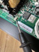
I have the Vantage speaker. When I try to lay down speaker on a side on the ground to install the isolation puck. After finish installation the puck, one of speaker suddently had no woofer. I can listen very low treble on ESL. I open the board and see one of capacitor on B&O 200ASC board that broken. That’s kind of weird sogn of defect.
You can see the picture as one of the attachment.
Do you know the value of capacitor that I red circle it?
Thanks in advanced.


You can see the picture as one of the attachment.
Do you know the value of capacitor that I red circle it?
Thanks in advanced.
Attachments
No I didn't solve it. By the way +/-12V cannot be ok because it works by taking reference from 47v output. I guess the problem is caused by feedback pin 2 of pwm chip. I want to test with new opto coupler if I have time.After years of them sleeping in storage, I'm finally starting to troubleshoot the modules I have on hand, from a couple of Rotel RMB-1512 amps. Most of the 200ASC have the capacitor extremely bulgy and a very very low volume (3 out of 4 so far, haven't looked at the others yet), so it's obvious they are problematic. 47V & +/-12V rails measure ok.
However, my 4th module has good capacitors, but the same problem as @erdimeter (did you solve it btw?)
If I recall correctly it worked ok for a few seconds when tested alone. I shut it down to plug a possibly faulty 200AC module, repowered and it was no longer working, and I now have around 15 to 17V on the 47V output. The +/-12V rails are ok, and I have no visible trace of anything burned or exploded. Only "hot" mark I have is under the big 5W resistor next to the speaker output but it was already present when it worked (those poor rotels were overdriven and overheating for years I guess)
If anyone can chime in on what could be a potential cause for that rail to be so low, it'd appreciate it a lot.
I'm currently buying all the "regular" spare parts : TVS diode L201, 470 & 330uF electrolytic capacitors, C313 10uF smd cap, even the big caps next to TR200 even though they seem ok.
Also, my ASC modules have some of the jumper bridges next to J3 soldered, not all of them in the same configuration. Is there a chart I could look at to figure what "settings" they correspond to ? I haven't seen anything in the datasheet and designer's manual.
So I just received my replacement components, glad to say that on the 12 modules I have (4 x 200ASC & 8 x 200AC), I was able to repair all of them minus one ASC by just replacing the 470uF, 330uF and C313 caps. Thanks to all of you for the various informations in that thread ! C313 being the source for a very low volume makes it so easy to repair
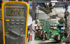
The one ASC that is not yet repaired is the one with the not working 47V rail (measures at around 17V). @erdimeter Weirdly enough, the +12V / -12V rails measure ok, but maybe they'll fail if I attach a load to it. I am getting 16VAC at the output of the T200 transformer instead of the 115VAC present on a working module, not sure that's an interesting bit of information.
The one ASC that is not yet repaired is the one with the not working 47V rail (measures at around 17V). @erdimeter Weirdly enough, the +12V / -12V rails measure ok, but maybe they'll fail if I attach a load to it. I am getting 16VAC at the output of the T200 transformer instead of the 115VAC present on a working module, not sure that's an interesting bit of information.
- Home
- Amplifiers
- Class D
- B&O ICEpower 200ASC pictures