Using the slightly lower rated jFET as the sink means that the upper amplifying jFET is running at just below 100% of Idss. This ensures that the upper jFET has a -ve Vgs and that appears as a small negative output offset at the output terminals.
A 1mA difference in jFET Idss will result in a big output offset.
Read D.Feucht on how to remove that output offset.
Add Rsu into the source leadout of the upper jFET.
A 1mA difference in jFET Idss will result in a big output offset.
Read D.Feucht on how to remove that output offset.
Add Rsu into the source leadout of the upper jFET.
Attachments
Last edited:
B1+ Copland CTA505 power amp
Hello all,
I am considering buying a Copland CTA505 amplifier.
Since I already have a built B1 preamp I was wondering:
- how will the B1 pre work with such an amplifier?
Hifiengine ( specs ) : Copland CTA505 - Manual - Valve Power Amplifier - HiFi Engine
Hello all,
I am considering buying a Copland CTA505 amplifier.
Since I already have a built B1 preamp I was wondering:
- how will the B1 pre work with such an amplifier?
Hifiengine ( specs ) : Copland CTA505 - Manual - Valve Power Amplifier - HiFi Engine
woody,
Don't worry about the slight deviation from 2/V, it's unimportant as this is a B1 and not a DCB1.
Don't worry about the slight deviation from 2/V, it's unimportant as this is a B1 and not a DCB1.
I just got my B1 Buffer board with matching JFETs.
Question: Can this be modified to eliminate the extra input (really only need one input) and avoid the selector switch and extra wiring? Is it a simple matter of a few jumper wires or something? Just wondered if someone has done this as a simplification.
Thanks!
Question: Can this be modified to eliminate the extra input (really only need one input) and avoid the selector switch and extra wiring? Is it a simple matter of a few jumper wires or something? Just wondered if someone has done this as a simplification.
Thanks!
I just got my B1 Buffer board with matching JFETs.
Question: Can this be modified to eliminate the extra input (really only need one input) and avoid the selector switch and extra wiring? Is it a simple matter of a few jumper wires or something? Just wondered if someone has done this as a simplification.
Thanks!
I just soldered a permanent jumper wire to input 1 where the selector switch would go -- others have done the same.
Single input
Would you happen to have a pic of your board with the jumper? Just one wire is all that's necessary?
Thanks!
Would you happen to have a pic of your board with the jumper? Just one wire is all that's necessary?
Thanks!
I just soldered a permanent jumper wire to input 1 where the selector switch would go -- others have done the same.
Odd question: But why delete what you don't need... Today?
Could be clever and simpler to build it and simply not use it..
until you need to 😉
Could be clever and simpler to build it and simply not use it..
until you need to 😉
Disabling the external switch actually requires adding 2 small jumpers. So nothing is being deleted... 😀
Sorry for the tiny photos, it's all I can find...
The jumpers are the bare wire bridges in the middle, from R2 and L2 to the unlabeled pads in the middle. Mostly obscured by blue wire... :/
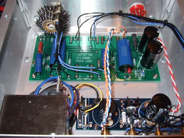
And you can see where the inputs attach, above those pads coming from the rotary switch.
EDIT - here's a bigger photo -
The jumpers are the bare wire bridges in the middle, from R2 and L2 to the unlabeled pads in the middle. Mostly obscured by blue wire... :/
And you can see where the inputs attach, above those pads coming from the rotary switch.
Would you happen to have a pic of your board with the jumper? Just one wire is all that's necessary?
Thanks!
EDIT - here's a bigger photo -
An externally hosted image should be here but it was not working when we last tested it.
Last edited:
A3 attenuator wiring
Would anyone be so kind to draw where the connections should be? I'm left 😕 since there are six volume connectors on the B1 however eight on the A3 attenuator.

Thanks
Would anyone be so kind to draw where the connections should be? I'm left 😕 since there are six volume connectors on the B1 however eight on the A3 attenuator.
Thanks
1) Please look at the traces on the a3 and see if each channel's G are connected.
2) b1 W and a3 OUT are connections. That I'm sure of.
3) b1 CW is most likely a3 IN
4) b1 CCW is most likely a3 G
Do this on both channels.
the worst that will happen is the pot will act backwards, if so, swap CW with CCW
2) b1 W and a3 OUT are connections. That I'm sure of.
3) b1 CW is most likely a3 IN
4) b1 CCW is most likely a3 G
Do this on both channels.
the worst that will happen is the pot will act backwards, if so, swap CW with CCW
1) Please look at the traces on the a3 and see if each channel's G are connected.
2) b1 W and a3 OUT are connections. That I'm sure of.
3) b1 CW is most likely a3 IN
4) b1 CCW is most likely a3 G
Do this on both channels.
the worst that will happen is the pot will act backwards, if so, swap CW with CCW
Thank you 6L6 I will try that. Looking at Ground it looks like each ground goes to a separate set of resistors and are not connected. I will try just hooking up one ground to see what happens.
The G are not connected? Strange.
Can you post the schematic? I'd like to see how it's made. I suspect it may not work properly with one set open...
In the time being, use the G near the output.
Can you post the schematic? I'd like to see how it's made. I suspect it may not work properly with one set open...
In the time being, use the G near the output.
6L6's wiring directions were spot on for the A3 attenuator. I'm powering mine with two 9v batteries wired in series and it sounds phenomenal. I only have 9400uf and will have 30,000uf when my Digi-Key order gets here. Much better than my old Denon 2808CI running as a preamp which died.
So far what I noticed immediately:
- The B1 just gets out of the way
- Sounds more dynamic when the movies/music calls for it.
- Chimes, bells, buzzes, swooshing of a coat. They all sound more noticeable and distinct.
Using a Luxman M-02 as the amp and Pioneer BS22 speakers. Must say I am impressed as I know these are not the best speakers yet I was able to notice the difference quite easily. Curious just how great it would be if I finished my DIY speakers or still owned my Energy Reference RC70 speakers.
Must admit though I think I am the first to use a cardboard box...
Last edited:
Just thought I would add that I would not recommend 9v batteries wired in series. It sounds phenomenal but not for long. The batteries will only last 1-2 days if not disconnected at night. Also, common sense for most but turn off the amp first or experience a large pop...So easy to accidentally forget that lol
Pros
- Sounds phenomenal at first
- Easy and safe
Cons
- Sound quality begins to diminish after only a few hours. I assume from the voltage dropping
- Only powers the B1 Buffer for 24-36 hours continuously
- It will last longer than 36 hours but will lose volume. Sooner or later volume is at max and sounds very flat. Eventually it will start crackling.
- 9v batteries are expensive when they only last a day or two
I would recommend two SLA 12v batteries wired in series instead. Upgrade the 25v filter caps to 35v first though.
- SLA batteries are rechargeable unlike most 9v batteries
- Outputs 24v in series and a voltage drop will not matter as much at all since 18v is the minimum.
- SLA batteries have 5-12 Amps while 9v batteries only have 500 mah
Last edited:
- Home
- Amplifiers
- Pass Labs
- B1 Buffer Preamp