It's just like a ported enclosure. The port is a tube. Tubes have resonances. The resonance is excited by any energy at the resonant frequency and is a standing wave inside the tube. The energy is supplied by the rushing of air in and out of the tube, which creates turbulence, which generates acoustic energy. The port resonance has a series of overtones, but they are higher in frequency than your plot shows and typically become lower in intensity compared to the fundamental self-resonance.Little or no experience with bandpass enclosures here, so trying to understand. Is the 650 hz peak generated primarily from a different, lower frequency in the desired bandpass region (like a multiple of a number)? Still it seems to me that the movement in the port requires a driving force at the resonant frequency. By greatly reducing the power provided to the driver at that frequency, wouldn't that affect the spl peak to some noticeable level?
Let's look at your plot again. The bandpass enclosure is itself a low pass filter. That is why it's a bandpass! The plot has the passband between about 40Hz and 150Hz, then it drops off above that as the LP filter effect of the bandpass kicks in. Then it rises again as the port self-resonance frequency is approached. After the peak of the resonance the SPL drops and will rise again at the second harmonic of the port resonance (off the plot, higher in frequency). If you extent the frequency in your plot higher, you will see a series of peaks and dips.
The tube self-resonance is different from the Helmholtz resonance created by the tube plus the box, the latter being the usual one that is "tuned" in a loudspeaker. Maybe that is where you are getting confused.
Last edited:
(I hate it when I type a bunch of stuff in the "Quick Reply" post box and then go back to an earlier page and lose all when I return.)
Anyway, yes I did get confused about using an EQ to fix an acoustical problem even though several posts back I mentioned that it was an acoustical problem.
So I think this is what I'm going to do:
1. build it and see how much of a problem it is. Put the tube on the outside and make it tunable before committing to it on the inside
2. Maybe make the port smaller in dia and therefore shorter to tamp down the peaks - give up some lower bass
3. Change/add the type and amount of stuffing in the enclosure
4. make the enclosures larger but that will be the last thing
5. place some stuffing in the tube and make it more aperiodic. Since I'm using a 3d printer to build the ports, maybe adding some friction to the tunnel will do the same thing - interesting to try
6. Give CharlieLaub's comment a shot about facing the port down into foam/rugs/etc at least 1.5 inches away
7. I don't know if this will work, but might try two ports.
8. and if time, maybe read the pdf that GM gave and build a chamber somewhere in the port area but that increases box vol so not sure about that.
9. or maybe adding a small speaker (I have 50+ from 1" to 15") somewhere along the tunnel. I wonder if that would work for that resonance as well as the others that follow???
Thanks guys,
scott
I have read that this is often used in automobile exhaust systems to quiet pipe resonances. I think this is one of the arguments for putting a driver 1/3 of the way along a closed pipe horn, or something like that. I'm a little fuzzy on the exact recollection.
Yep, I learned TL/horn theory primarily to design DIY hi-perf intake, exhaust systems and mufflers are just a bunch of musically tuned pipes wrapped in insulation.
Right ~two octaves away at the 3rd harmonic dip.
GM

Brian, GM,
The helmholz resonator sounds like an efficient solution. Thanks for the info.
You're welcome!
The vent is an open pipe, i.e. a 1/2 WL resonator with both even and odd harmonics, so can be quite musical when long enough to comb filter with the speaker's output: Resonances of open air columns
GM
Ok, I'm interested in learning how that peak and subsequent ones can be made less by a Helmholtz resonator. Are you suggesting a chamber off the tube? Would I need equipment or can it be done by math? I guess the chamber volume and where it would be placed in the tube would be what you need. How could we design an adjustable one where the reduction could be measured with a spl meter while playing a certain sine wave?
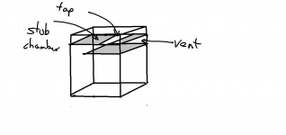
One other way is to add a resonator "stub" that's tuned to 650 Hz to the vent itself. I personally haven't tried this, but there is a thread across on the PE site somewhere where someone demonstrated how this was done for a small vented speaker with a long vent - he used a stub to tame the out of band resonance caused by the vent.
There is an old patent on this assigned to Yamaha.
Ok, I'm interested in learning how that peak and subsequent ones can be made less by a Helmholtz resonator. Are you suggesting a chamber off the tube? Would I need equipment or can it be done by math? I guess the chamber volume and where it would be placed in the tube would be what you need. How could we design an adjustable one where the reduction could be measured with a spl meter while playing a certain sine wave?
First, keep in mind that a Helmholtz resonator is a box and tube, like a vented speaker without the speaker driver. This requires some volume in and of itself, and that volume might be better used in the sub by increasing the front chamber volume.
If you want to try it just to see how it works, how effective it is, etc. then to answer your question about making an adjustable one, just use an adjustable port tube and have that sticking out of the box of the adsorber. As you change the port tube length you will also be changing the tuning.
It's a resonance. Wouldn't bracing it raise the frequency bump or change the shape making it easier to tame?
Brace what exactly?
I think you misunderstand the source of this resonance. Please see post #21.
Thanks GM, for that was a neat program about pipe resonances.
Yeah, the adjustable tube on the outside is a good way to tune the box. But there will still be resonances that probably will need to be damped. So how can we determine where there should be a "Stub" or a chamber, like on the thread I started on the full range forum, "Bose 1/4 wave patent."
If we can figure out where to place the "Stub", would using a T-Fitting in the pvc round tube work with an additional pipe sticking out of it?
How would we figure the volume of the "Stub?"
Bose has two chambers in their quarterwave channel (I assume for different harmonics) but would that principal apply to a port too?
Thanks GM, for that was a neat program about pipe resonances.
Yeah, the adjustable tube on the outside is a good way to tune the box. But there will still be resonances that probably will need to be damped. So how can we determine where there should be a "Stub" or a chamber, like on the thread I started on the full range forum, "Bose 1/4 wave patent."
If we can figure out where to place the "Stub", would using a T-Fitting in the pvc round tube work with an additional pipe sticking out of it?
How would we figure the volume of the "Stub?"
Bose has two chambers in their quarterwave channel (I assume for different harmonics) but would that principal apply to a port too?
If you want to implement the stub, be prepared to make a lot of adjustments...
In a regular tuned box (bandpass, vented box, etc) the length and diameter of the vent as well as the box volume all influence the tuning. The stub is a dead end pipe of some length, L3, connected somewhere along the total vent length Lv so that there is a length L1 between the connection point and the box, and a length L2 between the connection point and the "outside". Forgetting about the pipe diameter and box length for a moment, all three of these lengths may influence the tuning (the resonant frequency of the box+vent) as well as how the stub is interacting with the standing waves within the main tube. I'm not aware of closed-form equations for designing a vent+stub system, although there are probably rules of thumb. You can use a computer model to get in the ballpark, but you will very likely then need to tweak the lengths to get it to work well. You could use three adjustable ports (one tube slides over another). One end is the "adjustable end" and the other end is fixed. Connect all three together at their "fixed ends" and then adjust L1, L2, and L3 by adjusting the movable ends. For the stub, the movable end will be a termination, e.g. that end should be sealed off. This might give you enough flexibility to be able to fine tune the lengths after getting in the ball park. Still, because of the complex interaction between what you want (the stub should adsorb the resonance while maintaining the desired tuning frequency) and the lengths L1, L2, and L3 you might be doing a lot of small adjustments. If you can measure the system impedance and the vent output (the bandpass system output) and you keep a record of what you have done you can probably hone in on the right combination. That kind of system is pretty interesting, so I would be curious how it turns out if you try it.
Hey CharlieLaub, you seem to be quite an expert - thanks for the long explanation.
So here is what I will do in the next couple of months
1. build the system.
2. put an adjustable port on the outside
3. tune it to the bass I want
3. use a SPL meter, voltmeter and sine waves to see where I get a peak around the 300 to 800 range.
4. then place a pvc T fitting and another adjustable pipe in it
5. Now is there a program that will tell me where in the pipe to place that T. It seems to me that if I can find the peak and I know how long the main vent is, that somehow, using math, I should be able to determine the distance down the pipe to begin the trial. If we look a drawing of waves in a pipe, would the T fitting go at the top of the wave or at the trough?
thanks
If you implement the vent as a shelf vent at the bottom of the cabinet, then you could include a resonance "stub" chamber there as well. If you design the cabinet with easy access to the chamber in mind (make the outside panel removable), that should give you a means of easily making changes to the chamber to see what impact that has on dealing with the out of band peaks in the bandpass sub's response.
I was thinking of trying a similar approach in my next TH build (converting the back panel into a stub chamber, so I could do the same thing). I haven't "run the numbers yet" though.
I was thinking of trying a similar approach in my next TH build (converting the back panel into a stub chamber, so I could do the same thing). I haven't "run the numbers yet" though.
Attachments
It is important to understand that the resonance is NOT due to electronic input to the driver but due to the movement of air in and out of the port at low frequencies. Thus, adding a notch filter on the woofer/subwoofer driver in the BP enclosure will do nothing to reduce or eliminate the resonance.
Hi CharlieLaub,
I'm having trouble understanding this statement - On my BP6 sub that I use with my tv system a couple of parametric eq notches eliminate the resonances from the ports. According to this statement they would have no effect ?
Rob.
Hi CharlieLaub,
I'm having trouble understanding this statement - On my BP6 sub that I use with my tv system a couple of parametric eq notches eliminate the resonances from the ports. According to this statement they would have no effect ?
Rob.
Do you also have a crossover that rolls off power to the driver well below the port self-resonance? I was assuming this was the case...
If not, then the driver's own output will also excite the port resonance and your EQ notches will reduce it. But the resonance can still be excited when there is low frequency input to the BP system causing lots of air movement in the duct. If you test using a sweep you will not see this, because by the time the sweep reaches the port self-resonance frequency the low frequency energy has dies out. You would probably have to measure with wideband white noise to see it in your measurement.
It's a physical resonance of the port tube, so any energy at the resonant frequency reaching the port tube will make it resonate.
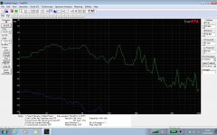
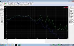
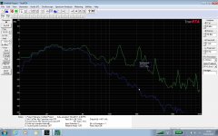
Here's 3 screenshots.
1st is unfiltered sub output with pink noise. (green trace in all 3 shots)
2nd is pink noise with lowpass filter (sub out) (blue trace)
3rd is pink noise with lowpass filter plus notch filters. (blue trace)
1st is unfiltered sub output with pink noise. (green trace in all 3 shots)
2nd is pink noise with lowpass filter (sub out) (blue trace)
3rd is pink noise with lowpass filter plus notch filters. (blue trace)
Attachments
Last edited:
Here's 3 screenshots.
1st is unfiltered sub output with pink noise. (green trace in all 3 shots)
2nd is pink noise with lowpass filter (sub out) (blue trace)
3rd is pink noise with lowpass filter plus notch filters. (blue trace)
What are the dimensions of your port?
What are the dimensions of your port?
Here's the info for both ports. As you can see the measured resonances are pretty close to the predicted ones.
Sorry to the OP for derailing this thread a bit.
I didn't see any port info, but I will take your word on it.
I think what is happening is that the resonances are so close to the driver passband that the driver's own output is still providing energy that is exciting the resonance(s) even after adding the LP filter. You can see that the area under the peak of the 110Hz resonance is about the same, and the 220Hz resonance is reduced slightly. The third one around 330Hz has been reduced in magnitude by about half because the driver output is 24dB down or more and this level is starting to be weak enough to provide to too little energy for much in the way of resonance to happen, but it's still there.
This is not quite the same as the case for the OP, where the first resonance is way up at 650Hz. Your first resonance is at 110Hz, and the driver is only down 10dB from your LP filter at that point. That's not all that much in absolute terms. -10dB = 1/3.16 ~ one third of the pressure. Even 20dB down, which seems like a lot, is only 1/10th the pressure.
By notching out the driver output at these frequencies you are probably killing off most of the energy from the driver output, much more than the LP filter alone. But like I mentioned before, there will still be some energy that can be generated by turbulent flow in the port at high output levels that can excite the port resonances just like when you blow over an empty bottle. This would be most noticeable on something with lots of LF energy (esp. below the F3 of the sub), where there is lots of air flow through the port. You can also use a HP filter there to reduce the electrical input at F<F3 if you want to prevent that kind of thing.
- Status
- This old topic is closed. If you want to reopen this topic, contact a moderator using the "Report Post" button.
- Home
- Loudspeakers
- Subwoofers
- bandpass port resonance elimination