I received an email from one of the participants in this thread asking about power supplies so I thought I would offer some suggestions here.
I started building "Champs" back in the 60's using parts salvaged from old TV's, radios and HiFi's. Every one was different since I used whatever parts I could find in the local trash dump. They all sounded different, even two made with nearly identical parts. As a teenage kid who liked to make noise and blow stuff up, I didn't know or care why.
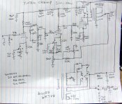
About 30 years later, when my daughter and her friends played guitar, I made a bunch of "Turbo Champs" from new and salvaged parts. They were thrown together on the fly without much thought, or even a schematic. They used whatever speaker and cabinet that I had, or felt like making at the time. Again, no two were alike. The last one was too clean for my tastes, or that of her friends, until a rhythm guitar player who used an ES335 fell in love with it, so I gave it to him. It is my belief that the 6 X 9 JBL car speakers (I took them out of a car that I was trading in) that I used in it were responsible for the ultra clean sound. That one used a KT88 on 450 volts. Some used the 6V6 type tube, while others used EL34's, 6L6GC's, and even KT88's. Most used power transformers and chokes salvaged from scrap HP audio oscillators. The Hammond 125CSE OPT allowed deliberate impedance mismatching for another element of tone control. After the last amp was gone, I attempted to draw the schematic from memory. It probably doesn't match any of them exactly, but it contains some concepts that can be applied to any "Champ" type amp. The 100 uF and 47 uF power supply caps shown were only used in the clean amp, the others had smaller caps. The values of the switchable cathode bypass caps are only a guess. The actual values will depend on the speaker, guitar, and playing style used. Ditto some resistor values.
50+ years of noise and blowing stuff up have transpired, and now I understand why things happened the way they did back then. Some observations:
The Champ circuit is a class A Single Ended amp design. It has been said that "sag" and other power supply aspects don't matter in a class A guitar amp since a class A amp always draws the same current whether it is at idle, or full output. That is technically a true statement, but as soon as you plug in a Tone Bender or Fuzz face and set it on KILL, that Champ isn't class A anymore and the output tube current will be all over the place!
The average tube current in an SE amp usually drops as the amp clips, but this is not always the case. The tube current skyrockets if the OPT saturates. Early Fender Champs had a TINY OPT that saturated on bass notes.
The speaker, and how its impedance changes with frequency has a MAJOR influence on OPT saturation.
The early Champs had a rather stiff small speaker with limited low frequency response. Some hum could be tolerated in the amp design if the speaker couldn't reproduce it.
Hum in the PLATE supply on a pentode output stage doesn't always show up in the output when the amp is in class A operation (clean playing). Hum in the screen supply WILL be present in the output. Some hum in the plate supply is what causes the growling overload sound when the amp it mildly overdriven. A big fat first supply cap (on the red lead of the OPT) kills this tone. That's why some prefer smallish supply caps(5 to 20 uF).
When the output tube draws excessive current, the power supply voltage drops. This condition is called "sag". If you blast off a big power chord through a pedal with lots of gain driving the amp into clipping, the power supply drops. This lowers the gain of the entire amp, including the preamp. As the chord dies out, the overload begins to clear, and the power supply voltage starts to rise. The power supply caps down stream will recharge more slowly since there are resistors between them and the rectifier tube. The size of the resistors, and the cap values will affect the amps recovery time, and thus its "sustain".
The size of the power transformer, the rectifier tube, filter cap values, and the screen resistor on the output tube affect this the most. Experiment with these to suit the tone you are searching for. The 5Y3 has the most sag, the 5AR4 the least. The 5U4 is in between, IF your power transformer has a 3 amp rating on the 5 volt winding. Solid state diodes have near zero sag. Too big of a power transformer kills the sag.
The current limiting resistor in the mosfet VVR can be used to adjust the sag. The capacitor added to the gate circuit will affect the recovery timing.
A little bit about distortion:
As an amplifier stage approaches clipping it begins to distort the signal. There are two primary types of distortion that gets discussed, and a bunch of secondary effects important to the HiFi guys.
The first is harmonic distortion. Pure harmonic distortion adds new notes to the sound that are integer multiples of the original notes frequency. The even numbered harmonics are ALL higher octave copies of the original note. The second harmonic (twice the frequency) of C2 is C3, and the 4th harmonic is C4. The odd numbered harmonics are not all musically related, and excessive levels of higher ordered (5th, 7th, and higher) harmonics begin to sound out of place or dissonant. Reasonable amounts of harmonic distortion sound musically pleasing, and impart a "brighter" timbre on the sound. The distortion produced by an amp, even cranked to 11, when fed a SINGLE NOTE, is primarily harmonic distortion. The sum of all the harmonic distortion is called Total Harmonic Distortion (THD) and usually expressed as a percentage of the amps total output.
The second type is intermodulation distortion, or IMD. When two or more notes are fed to the same amplifier, they will mix together to produce two new notes that are not usually musically related. These two new notes are the sum and difference between the frequencies of the original notes. Thus if you feed amp middle C at about 262 Hz and A above middle C at 440 Hz, two new tones tones will be generated, the sum at 702 Hz and the difference at 178 Hz. Notice that these frequencies fall in between musical notes, and WILL sound dissonant. IMD sounds bad, almost always.......Almost? IMD, is the reason for Power Chords. Power chords are built so their IMD frequencies fall close enough to notes to sound good.
IMD and THD travel together, it is rare to find one without the other whenever two or more notes are played, so excessive distortion with multiple notes, even power chords can sound bad, because new tones will be generated by the IMD between each of the harmonics created by the THD. Two notes stuffed through an overly distorted system can produce hundreds of offspring notes sounding like music in a blender....because it IS!
Many guitar players and amp builders search for "touch sensitivity." This is the ability to change the amps character and tone by playing harder, or gently nudging the guitar's volume control. An amp right on the edge of clipping has some degree of touch sensitivity, the quiet passages are clean, while the louder notes are somewhat distorted. How can we improve on this? The most common method is the master volume control. It, along with the input volume control can be adjusted, such that as the guitar is turned up, or played harder, the output stage starts to clip, then as a bit more signal is applied the gain stage before the master volume begins to clip as the output stage is reaching full distortion without being nasty (minimal IMD). Any further input from the guitar will saturate the input stages of the amp without full on nastiness from the output stage. We want gentle THD from each stage without excessive IMD. Some amps (Soldano comes to mind) wire several stages together successively with attenuation in between, such that they distort in reverse order to generate huge amounts of touch sensitivity IF all is set up right and the player can control it.
As many guitar players have learned, the lower frequency notes seem to tax the amplifier more than the higher frequency notes. The OPT and the speakers are the primary reasons for this.
Note that IMD always produces a low frequency note, and a high frequency note. The lower frequency notes will go through the amp using up some of its dynamic range, only to produce an unwanted note. The tone stack can't kill these notes if they are generated after the tone stack.
Hifi amp designers use large valued coupling caps to allow for response down into the low tens of Hz. We don't want this in a guitar amp. The lowest note on a guitar using standard tuning is about 82 Hz. The coupling caps should be sized to pass this frequency without much loss, but anything lower is usually not needed, or wanted in a guitar amp. This reduces "muddy tone" and often the 3 dB point is set a bit higher, especially in an amp with small speakers or OPT. I use .047uF or .022uF coupling caps in most amps, sometimes even smaller.
The cathode bypass caps also affect the amps low frequency response. Avoid huge cathode caps.
Someone suggested raising the grid resistor on the output tube to 470K or higher to increase gain. Be careful with this resistor value, especially with new production Russian or Chinese output tubes. Too large a resistor here can cause the tube to go into red plate runaway and self destruct. This is more common on amps that run a lot of B+ voltage or get played hard (a lot of clipping). A big resistor here can cause blocking distortion (farting out) if the amp is overdriven a lot. Putting a pot here, as long as it isn't too high of value, can be a simple way to add a master volume, and it shouldn't affect bias. It will affect tone if it is turned down too low (reduces bass).
Purposefully mismatching the speaker load (the 125CSE OPT and switch) will allow a few unusual tones, and is generally safe unless taken too far. There should be no issue at all on a Champ sized amp.
Sticking frequency selective circuitry in the feedback path creates a new tonal palette that has not been commercially exploited yet, beyond the simple presence control, to my knowledge. The simple cap - resistor - pot circuit shown in the Turbo Champ schematic adds some texture. Putting a full FMV tone stack there can lead to some rather unusual sounds, and TOTAL amp instability. The usual tone stack has enough phase shift to turn negative feedback into positive feedback, making the amp oscillate. It does sound totally cool right on the edge, like the resonance knob on an analog synth, but beware......proceed at your own risk.
The tone stack in the main signal path is a subject that could fill a book. The Baxandall stack, as used in the Hifi world is set up for the extremes in frequency. The treble knob operates too far out in the high frequency extreme for guitar use. The bass does too, but not as bad. It could probably work with some value tweaks. Maybe a simulation expert can help here.
Generally we don't need, or even want a flat frequency response for electric guitar, especially lead guitar. A rhythm or keyboard player might want a flat response, and a Baxandall stack would work for them.
The amount of cut, boost, and "midrange scoop" is highly dependent on the speakers and playing style of the user. What sounds good for a country player using a Telecaster, may sound rather strange with a cranked Strat playing a screaming lead.
The typical FMV tone stack has about 20 dB of signal loss, depending on settings. It takes almost one stage of 12AX7 gain to recover that loss. As stated earlier, this is why many simple amps use one knob tone controls.
I have used the simple one knob tone control shown in the 4 tube amp schematic in several designs. It has less loss than the typical FMV tone stack, but still has too much loss for a two stage amp (one dual tube). This amp was designed for the Hundred Buck Amp Challenge at the top of this forum, and full details are buried somewhere in that thread. The amp has since been modified for switchable SE or P-P operation with a mosfet phase splitter. I will eventually post the new design here somewhere, once I find the amp. It's in a moving box somewhere.......
I also included the Turbo Champ schematic.
I started building "Champs" back in the 60's using parts salvaged from old TV's, radios and HiFi's. Every one was different since I used whatever parts I could find in the local trash dump. They all sounded different, even two made with nearly identical parts. As a teenage kid who liked to make noise and blow stuff up, I didn't know or care why.
About 30 years later, when my daughter and her friends played guitar, I made a bunch of "Turbo Champs" from new and salvaged parts. They were thrown together on the fly without much thought, or even a schematic. They used whatever speaker and cabinet that I had, or felt like making at the time. Again, no two were alike. The last one was too clean for my tastes, or that of her friends, until a rhythm guitar player who used an ES335 fell in love with it, so I gave it to him. It is my belief that the 6 X 9 JBL car speakers (I took them out of a car that I was trading in) that I used in it were responsible for the ultra clean sound. That one used a KT88 on 450 volts. Some used the 6V6 type tube, while others used EL34's, 6L6GC's, and even KT88's. Most used power transformers and chokes salvaged from scrap HP audio oscillators. The Hammond 125CSE OPT allowed deliberate impedance mismatching for another element of tone control. After the last amp was gone, I attempted to draw the schematic from memory. It probably doesn't match any of them exactly, but it contains some concepts that can be applied to any "Champ" type amp. The 100 uF and 47 uF power supply caps shown were only used in the clean amp, the others had smaller caps. The values of the switchable cathode bypass caps are only a guess. The actual values will depend on the speaker, guitar, and playing style used. Ditto some resistor values.
50+ years of noise and blowing stuff up have transpired, and now I understand why things happened the way they did back then. Some observations:
The Champ circuit is a class A Single Ended amp design. It has been said that "sag" and other power supply aspects don't matter in a class A guitar amp since a class A amp always draws the same current whether it is at idle, or full output. That is technically a true statement, but as soon as you plug in a Tone Bender or Fuzz face and set it on KILL, that Champ isn't class A anymore and the output tube current will be all over the place!
The average tube current in an SE amp usually drops as the amp clips, but this is not always the case. The tube current skyrockets if the OPT saturates. Early Fender Champs had a TINY OPT that saturated on bass notes.
The speaker, and how its impedance changes with frequency has a MAJOR influence on OPT saturation.
The early Champs had a rather stiff small speaker with limited low frequency response. Some hum could be tolerated in the amp design if the speaker couldn't reproduce it.
Hum in the PLATE supply on a pentode output stage doesn't always show up in the output when the amp is in class A operation (clean playing). Hum in the screen supply WILL be present in the output. Some hum in the plate supply is what causes the growling overload sound when the amp it mildly overdriven. A big fat first supply cap (on the red lead of the OPT) kills this tone. That's why some prefer smallish supply caps(5 to 20 uF).
When the output tube draws excessive current, the power supply voltage drops. This condition is called "sag". If you blast off a big power chord through a pedal with lots of gain driving the amp into clipping, the power supply drops. This lowers the gain of the entire amp, including the preamp. As the chord dies out, the overload begins to clear, and the power supply voltage starts to rise. The power supply caps down stream will recharge more slowly since there are resistors between them and the rectifier tube. The size of the resistors, and the cap values will affect the amps recovery time, and thus its "sustain".
The size of the power transformer, the rectifier tube, filter cap values, and the screen resistor on the output tube affect this the most. Experiment with these to suit the tone you are searching for. The 5Y3 has the most sag, the 5AR4 the least. The 5U4 is in between, IF your power transformer has a 3 amp rating on the 5 volt winding. Solid state diodes have near zero sag. Too big of a power transformer kills the sag.
The current limiting resistor in the mosfet VVR can be used to adjust the sag. The capacitor added to the gate circuit will affect the recovery timing.
A little bit about distortion:
As an amplifier stage approaches clipping it begins to distort the signal. There are two primary types of distortion that gets discussed, and a bunch of secondary effects important to the HiFi guys.
The first is harmonic distortion. Pure harmonic distortion adds new notes to the sound that are integer multiples of the original notes frequency. The even numbered harmonics are ALL higher octave copies of the original note. The second harmonic (twice the frequency) of C2 is C3, and the 4th harmonic is C4. The odd numbered harmonics are not all musically related, and excessive levels of higher ordered (5th, 7th, and higher) harmonics begin to sound out of place or dissonant. Reasonable amounts of harmonic distortion sound musically pleasing, and impart a "brighter" timbre on the sound. The distortion produced by an amp, even cranked to 11, when fed a SINGLE NOTE, is primarily harmonic distortion. The sum of all the harmonic distortion is called Total Harmonic Distortion (THD) and usually expressed as a percentage of the amps total output.
The second type is intermodulation distortion, or IMD. When two or more notes are fed to the same amplifier, they will mix together to produce two new notes that are not usually musically related. These two new notes are the sum and difference between the frequencies of the original notes. Thus if you feed amp middle C at about 262 Hz and A above middle C at 440 Hz, two new tones tones will be generated, the sum at 702 Hz and the difference at 178 Hz. Notice that these frequencies fall in between musical notes, and WILL sound dissonant. IMD sounds bad, almost always.......Almost? IMD, is the reason for Power Chords. Power chords are built so their IMD frequencies fall close enough to notes to sound good.
IMD and THD travel together, it is rare to find one without the other whenever two or more notes are played, so excessive distortion with multiple notes, even power chords can sound bad, because new tones will be generated by the IMD between each of the harmonics created by the THD. Two notes stuffed through an overly distorted system can produce hundreds of offspring notes sounding like music in a blender....because it IS!
Many guitar players and amp builders search for "touch sensitivity." This is the ability to change the amps character and tone by playing harder, or gently nudging the guitar's volume control. An amp right on the edge of clipping has some degree of touch sensitivity, the quiet passages are clean, while the louder notes are somewhat distorted. How can we improve on this? The most common method is the master volume control. It, along with the input volume control can be adjusted, such that as the guitar is turned up, or played harder, the output stage starts to clip, then as a bit more signal is applied the gain stage before the master volume begins to clip as the output stage is reaching full distortion without being nasty (minimal IMD). Any further input from the guitar will saturate the input stages of the amp without full on nastiness from the output stage. We want gentle THD from each stage without excessive IMD. Some amps (Soldano comes to mind) wire several stages together successively with attenuation in between, such that they distort in reverse order to generate huge amounts of touch sensitivity IF all is set up right and the player can control it.
As many guitar players have learned, the lower frequency notes seem to tax the amplifier more than the higher frequency notes. The OPT and the speakers are the primary reasons for this.
Note that IMD always produces a low frequency note, and a high frequency note. The lower frequency notes will go through the amp using up some of its dynamic range, only to produce an unwanted note. The tone stack can't kill these notes if they are generated after the tone stack.
Hifi amp designers use large valued coupling caps to allow for response down into the low tens of Hz. We don't want this in a guitar amp. The lowest note on a guitar using standard tuning is about 82 Hz. The coupling caps should be sized to pass this frequency without much loss, but anything lower is usually not needed, or wanted in a guitar amp. This reduces "muddy tone" and often the 3 dB point is set a bit higher, especially in an amp with small speakers or OPT. I use .047uF or .022uF coupling caps in most amps, sometimes even smaller.
The cathode bypass caps also affect the amps low frequency response. Avoid huge cathode caps.
Someone suggested raising the grid resistor on the output tube to 470K or higher to increase gain. Be careful with this resistor value, especially with new production Russian or Chinese output tubes. Too large a resistor here can cause the tube to go into red plate runaway and self destruct. This is more common on amps that run a lot of B+ voltage or get played hard (a lot of clipping). A big resistor here can cause blocking distortion (farting out) if the amp is overdriven a lot. Putting a pot here, as long as it isn't too high of value, can be a simple way to add a master volume, and it shouldn't affect bias. It will affect tone if it is turned down too low (reduces bass).
Purposefully mismatching the speaker load (the 125CSE OPT and switch) will allow a few unusual tones, and is generally safe unless taken too far. There should be no issue at all on a Champ sized amp.
Sticking frequency selective circuitry in the feedback path creates a new tonal palette that has not been commercially exploited yet, beyond the simple presence control, to my knowledge. The simple cap - resistor - pot circuit shown in the Turbo Champ schematic adds some texture. Putting a full FMV tone stack there can lead to some rather unusual sounds, and TOTAL amp instability. The usual tone stack has enough phase shift to turn negative feedback into positive feedback, making the amp oscillate. It does sound totally cool right on the edge, like the resonance knob on an analog synth, but beware......proceed at your own risk.
Any thoughts on a Baxandall stack? Us guys over in the HiFi world love it.
The tone stack in the main signal path is a subject that could fill a book. The Baxandall stack, as used in the Hifi world is set up for the extremes in frequency. The treble knob operates too far out in the high frequency extreme for guitar use. The bass does too, but not as bad. It could probably work with some value tweaks. Maybe a simulation expert can help here.
Generally we don't need, or even want a flat frequency response for electric guitar, especially lead guitar. A rhythm or keyboard player might want a flat response, and a Baxandall stack would work for them.
The amount of cut, boost, and "midrange scoop" is highly dependent on the speakers and playing style of the user. What sounds good for a country player using a Telecaster, may sound rather strange with a cranked Strat playing a screaming lead.
The typical FMV tone stack has about 20 dB of signal loss, depending on settings. It takes almost one stage of 12AX7 gain to recover that loss. As stated earlier, this is why many simple amps use one knob tone controls.
I have used the simple one knob tone control shown in the 4 tube amp schematic in several designs. It has less loss than the typical FMV tone stack, but still has too much loss for a two stage amp (one dual tube). This amp was designed for the Hundred Buck Amp Challenge at the top of this forum, and full details are buried somewhere in that thread. The amp has since been modified for switchable SE or P-P operation with a mosfet phase splitter. I will eventually post the new design here somewhere, once I find the amp. It's in a moving box somewhere.......
I also included the Turbo Champ schematic.
Attachments
The speaker, and how its impedance changes with frequency has a MAJOR influence on OPT saturation.
The early Champs had a rather stiff small speaker with limited low frequency response. Some hum could be tolerated in the amp design if the speaker couldn't reproduce it.
...
As many guitar players have learned, the lower frequency notes seem to tax the amplifier more than the higher frequency notes. The OPT and the speakers are the primary reasons for this.
This coincides quite nicely with boobtube's previous comment about the bass response. Small OPT + speaker = poor bass response. At least that's what I gleaned from a quick google search. Time for more research!
The amount of cut, boost, and "midrange scoop" is highly dependent on the speakers and playing style of the user. What sounds good for a country player using a Telecaster, may sound rather strange with a cranked Strat playing a screaming lead.
The typical FMV tone stack has about 20 dB of signal loss, depending on settings. It takes almost one stage of 12AX7 gain to recover that loss. As stated earlier, this is why many simple amps use one knob tone controls.
I also included the Turbo Champ schematic.
Gotta have that scoop! I was just really interested in the Bax tonal control due to its prevalence. I'm taking a similar approach to the amp world that I have in the car world. Might be a bit unorthodox but a de-stroked 400 with a powerglide makes a REALLY fast 1/4 mile car 😀 Also as Paul had mentioned earlier, I'm all about learning out loud.
Thanks for stopping in, Remind me sometime that I'll have to buy you a beverage of choice if I'm in your city 😎
Might be a bit unorthodox but a de-stroked 400 with a powerglide makes a REALLY fast 1/4 mile car
350 crank in a 400 block, nothing too unorthodox about that. Powerglide, with a high revving 377 in a light car, OK it will work....just scream through the traps at 7000 RPM.
As with going fast, making a simple guitar amp is full of choices. What works for one person may suck for the next guy.
My last trip down the 3200 was with a FWD Dodge 2.2L 4 cylinder with a big turbo and a lot of boost. It really irritated the 5.0 Stang Bangers.....That was in the early 90's. Progress came, the drag strip closed down and was paved over to make the parking lot for a strip mall.......which is now mostly abandoned.
Moroso Motorsports Park was a 72 mile trip each way. Never made it there in my big block Challenger, 727 3 speed auto with 3.91 gears......I'd have to go 55 MPH. Sold that car when I moved here......hated to se it go.
Someone suggested raising the grid resistor on the output tube to 470K or higher to increase gain. Be careful with this resistor value, especially with new production Russian or Chinese output tubes. Too large a resistor here can cause the tube to go into red plate runaway and self destruct. This is more common on amps that run a lot of B+ voltage or get played hard (a lot of clipping). A big resistor here can cause blocking distortion (farting out) if the amp is overdriven a lot. Putting a pot here, as long as it isn't too high of value, can be a simple way to add a master volume, and it shouldn't affect bias. It will affect tone if it is turned down too low (reduces bass).
Couldn't this blocking distortion be alleviated by using a larger grid stopper than the 1.5k, say a 20-40k? Also, as I understand it, since Miller capacitance is all but non-existent in a pentode, there should be no worry about high frequency loss when increasing this value?
Not that it matters much but I did suggest the pot as an alternative. This should be an audio taper pot, correct? Thanks, always nice to get your insights!
Last edited:
Attached is the schematic of my latest version of my first build, the 5F1 Champ. Had a pot on the NFB but went to a 2-pos switch, and added a simple lo-loss treble-cut tone circuit (gets plenty "bright" due to proper no-hi-cut caps anywhere). Low-cost transformers, boosting B+ with a bridge rectifier. Lowered input resistor from 68K to 33K. And put a good Jensen speaker in it. Mounted it all in a SS Squire cabinet. Offering it as a good starting point. Have fun!
Attachments


This thread just went to 11 thanks to tubelab.com! Amazingly detailed post. Very much appreciated.
I modeled the power supply as best I could (attached) based on the 372BX PT and 194B choke. ***IF*** I have done it right, it seems the C3 voltage is very low at 207V. I believe it should be over 300V if C1/C2 are close to 380V (which is probably high for C2).
Thoughts?
If I keep the same PT, but change the choke to a 154G (9H,700ohm) and the resistor to 7.5k the voltages end up at:
C1 - 376
C2 - 357
C3 - 305
Attachments

Last edited:
Couldn't this blocking distortion be alleviated by using a larger grid stopper than the 1.5k, say a 20-40k? Also, as I understand it, since Miller capacitance is all but non-existent in a pentode, there should be no worry about high frequency loss when increasing this value?
Increasing the value of the grid stopper is a good way to reduce or eliminate blocking distortion. I have used 15K on an SE pentode EL84 guitar amp with good results.
I tried to go over the major influences on tone from all the parts in a champ style amp, but I am sure that I forgot to mention a lot more stuff.
Gibson built some similar style amps, with differences. The amp I had used a 6AQ5 output tube. It is common and is a scaled down 6V6. A valid choice for a small amp.
They also used a 6X4 rectifier. This allows the rectifier to operate on the same heater windings as the other tubes making the power transformer cheaper. The 6X4 has less sag than a 5Y3.
Gibson also built small amps with EL84 / 6BQ5 output tubes. They have a different tone than the 6V6 and 6AQ5 tube.
I have said this before, it is a generalization, but is true overall.....EL84's ROCK, while 6V6's sing the blues!
Well today I just received a care package from a member here. Got some pretty interesting tubes out of it along with some other awesome stuff (PT's, caps, etc). So begins the journey of the FRANKENCHAMP (spooooky!).
I've got a 6SL7 picked out for the first two stages and a 12L6 picked out for the output. One of the PT's I've got will work and I think I'll buy a XSE18-8-3.5k for the OPT.
Will be kind of cool to see how this turns out and I'm excited to get going on it!
I've got a 6SL7 picked out for the first two stages and a 12L6 picked out for the output. One of the PT's I've got will work and I think I'll buy a XSE18-8-3.5k for the OPT.
Will be kind of cool to see how this turns out and I'm excited to get going on it!
boobtube said:If you want to report on YOUR amp, you should start a new thread.
Well looks like I'll make like a tree and leaf then. Sorry that i thought since we were all in this together and that I'm going to be following the same schematic that paul will be just with a few minor variances that someone might want to know.
Maybe its the derrivance from the 12**7 and the 6v6 that's throwing you...idk....either way, I'm out.
That post was up for one minute and I thought better of it and took it down. But I also thought it was pretty crummy of you to only post part of what I posted just to make it sound worse than it was. You just took one part of it as the rest of it was just explaining that this was about Lightreel's amp. There is nothing wrong with starting your own thread if you are starting a new build. Your response seems a little childish to me. BTW, I do know the difference in the tubes, Jeez. If you want people to know about your amp, start a new thread instead of taking your ball and going home.
Last edited:
The original Champion circuit with a grid-leak biased pentode input stage is real interesting also.
@Joe: do you have a schematic for that Champion? Sounds interesting.
That is the circuit that I started out with in the mid 60's. 6SJ7's and sometimes 6V6's could be plucked from old radios in the trash for free. 12AX7's were not too common for free. As I learned how things worked, I abandoned grid leak bias. I would advise using a standard cathode resistor bias setup for any pentode input stage. See the hundred buck amp challenge (HBAC) schematic I posted earlier for details.
The grid leak bias setup uses a large value resistor to generate a negative voltage on the grid, while the cathode is grounded. This negative voltage is generated by collecting a few electrons from the space charge around the cathode and "leaking" some of them to ground through the 5 meg resistor. This voltage DEPENDS on a very good vacuum in the tube, since any "gas" will create grid current cancelling the negative bias. Current production tubes don't always have an excellent vacuum, and any 6SJ7 around today, has been around for at least 50 years, and may not have a great vacuum either.
Fender used it because it was cheap. It worked then, because the stomp box had not yet been invented. As I discovered when I built my first germanium Tone Bender clone (about 1970), the old Champ clone I had made years earlier could be made to go silent with a good blast from the two transistor stomp box, yet the stomp box worked great with a Bandmaster. I did not understand blocking distortion back then, but it was happening big time. The stomp boxes we have today have far more gain.
That post was up for one minute and I thought better of it and took it down......either way, I'm out......start a new thread instead of taking your ball and going home
This thread wasn't started by either of you. I thought it could be a good place to share ideas in a manner similar to the Hundred Buck Amp Challenge (HBAC) thread was a few years ago. That's why I came here.
Yes, there were some heated nasty moments in that thread too, but in the end, it was a year long discussion on cheap amp designs, and everybody played along. I have an 18 Watt Marshall clone with about $80 worth of parts in it that rocks, and a simple 4 tube amp that costs about $40. There were about 10 totally different designs from that thread for people to pick and choose from.
Anyone any thoughts on the "best" schematic for this?
The OP asked what the "best" choice for a simple "Champ" type schematic is. Truth is there is no "best" because that depends on the users opinion. I for one have probably built 20 or 30 Champ type amps in my lifetime. and really don't want to make another one, but if enough people stick around here, try something, and maybe post a Youtube video of some sound files, something cool could come of this thread that could be useful for everyone, or at least some people. If we all packed up and started our own new threads, they would all get lost in the noise and very few would know what happened.
I have been around this forum for 10 years. I have been a part of lot's of threads. Sometimes it was to answer a simple question, and I have forgotten those. The threads where dozens of people contributed ideas and something cool got created....classics.
The HBAC (at the top of this forum) is one of those. It is long, but recommended reading if you want to learn how to make a cheap 1 to 5 watt guitar amp. Some are simple, some not so simple, most with a good idea or two.
http://www.diyaudio.com/forums/instruments-amps/190738-hundred-buck-amp-challenge.html
The "red board thread" was started by another amp designer who designed a mild mannered 18 WPC stereo amp. I modified the design to make several high powered amps (up to 525 watts) and everybody learned about TV sweep tubes, and BIG power, yes I play my guitar through it. The design is applicable to high powered amp design, and probably useful reading.
http://www.diyaudio.com/forums/tube...p-p-power-amp-design.html?highlight=6L6GC+AB2
The 6L6GC in AB2 thread. A guy in Australia asked a question about amp design. The thread evolved into a total amp design spread across the globe. I proposed circuits, he built them, several people assisted, the amp was done. An excellent example of cooperative design.
http://www.diyaudio.com/forums/tubes-valves/133034-6l6gc-ab2-amp.html?highlight=6L6GC+AB2
I lost my electrical engineering job of 41 years last year, and put my house up for sale. It sold in a few days and the new owner didn't care what mess I left behind, so I basically walked away. 1200 miles away. Now, over a year later, I'm in a new house with a big empty basement. I am currently building workbenches, and all my equipment, old amps, tubes, and "stuff" is stashed in boxes in several places. I won't be building much anytime soon, but I do plan on getting back to some simple guitar amp designs when the new lab is done......and an analog synth or two.
Can we all get along here?
Attachments

That post was up for one minute and I thought better of it and took it down. But I also thought it was pretty crummy of you to only post part of what I posted just to make it sound worse than it was. You just took one part of it as the rest of it was just explaining that this was about Lightreel's amp. There is nothing wrong with starting your own thread if you are starting a new build. Your response seems a little childish to me. BTW, I do know the difference in the tubes, Jeez. If you want people to know about your amp, start a new thread instead of taking your ball and going home.
We'll leave it at that then. I'm sorry I got a bit fired but I'm following the same path paul is. His original postings had the same kind of excitement about this project that I've had for some time. we're both working through this at the same time and I'm really looking forward to seeing how each one turns out tonaly. Was a bit thrown off being told to "go play in my own corner". But we can leave it at that and move on eh?
.... 6SJ7's....
What's you're thought on this guy in a champ-style scheme? I'll admit that I'm not fluent in the different types but from a quick google i gleaned a bit earlier this evening (as i received some of these as well!). It sounds like they're a very linear tube but due to the "sharp cutoff" it sounds like there's a considerably more narrow range of operation to them. I also *thought* I found some literature that the ORIGINAL champ actually used the 6SJ7's and then they switched to the 12ax7 after a few iterations.
It looked like an interesting tube so I'm curious to how it may perform. Once I get the ckt built I might just switch it out with a few others I have laying around out of curiosity to see *tonaly* how my "but-dyno" is between them. There's just so many different tubes we can use in the ckt and im pretty excited to see what...could drive who...where. 😀
I leave you alone for TWO minutes and ... ;-) ...
There's plenty of room in here guys!
I started the thread looking for opinions, suggestions and experiences; as I'm very aware that "best" (in inverted commas) is highly subjective. Everyone here has contributed greatly on those fronts and helped me distill what I'm looking for. I'm as excited to read about others' past and future projects as I am to write about mine and I hugely appreciate those more technically gifted guiding me along.
I'm working on my layout now and will post some rough sketches later!
We'll leave it at that then. I'm sorry I got a bit fired but I'm following the same path paul is. His original postings had the same kind of excitement about this project that I've had for some time. we're both working through this at the same time and I'm really looking forward to seeing how each one turns out tonaly. Was a bit thrown off being told to "go play in my own corner". But we can leave it at that and move on eh?
What's you're thought on this guy in a champ-style scheme? I'll admit that I'm not fluent in the different types but from a quick google i gleaned a bit earlier this evening (as i received some of these as well!). It sounds like they're a very linear tube but due to the "sharp cutoff" it sounds like there's a considerably more narrow range of operation to them. I also *thought* I found some literature that the ORIGINAL champ actually used the 6SJ7's and then they switched to the 12ax7 after a few iterations.
It looked like an interesting tube so I'm curious to how it may perform. Once I get the ckt built I might just switch it out with a few others I have laying around out of curiosity to see *tonaly* how my "but-dyno" is between them. There's just so many different tubes we can use in the ckt and im pretty excited to see what...could drive who...where. 😀
Apologies from me as well. I was hoping you didn't see that post as I first saw it as maybe being more about your amp than Lightreel's. My first impression was thread hijacking but then I realized it was similar to the Camp/ Princeton, so I removed it ASAP. Lightreel has a mostly working schema, so I thought it was about your amp, not his. But I also didn't see starting your own thread as a " go play in your own corner" thing either. There are many times this has happened where a spinoff from a thread turned out to be quite informative, so I thought you might have more to offer telling us about your own amp. More an opportunity than anything else. But when all is said and done, I'm glad you are back and we can move on!
And you are correct, the 5C1 Champ did indeed have a 6SJ7 for the preamp, and since it's a pentode, under normal conditions will sound different than the two triode stages of the 6SL7. Of course it will depend on what voltage you operate the plate and screen at on that 6SJ7 to determine gain. Higher screen voltage will have more effect than higher plate voltage. Yes, it is more linear as the plate curves are more evenly spaced and when cutoff occurs from more neg signal, it is more sudden than the more gradual cutoff of a remote or semi-remote cutoff pentodes. Also, since there will be more gain in the input with a pentode, the noise that is generated will be higher because of the higher gain. so some people use a single triode for the input and then follow up with a pentode.
Last edited:
Hi guys, I revisited the v3 schematic and noticed it needs a coupling cap between 1st stage and the moonlight tone stack. Otherwise you just have resisters between B+ and ground, which doesn't happen in an FMV tonestack.
Hi guys, I revisited the v3 schematic and noticed it needs a coupling cap between 1st stage and the moonlight tone stack. Otherwise you just have resisters between B+ and ground, which doesn't happen in an FMV tonestack.
This guy right here.
I totally missed the interstage coupling cap on the v3 as well. Good catch...that may have resulted in some rather...erm....interesting effects
Since I'm using a different pentode I'm en-process of figure out all my loads and so-forth. ******* pentodes are silly......
Per my napkin scribbles however, the first stage should work with the given values if I use the 6SL7. I'm upping my cathode resistor though to a 1.8k for the grid bias I want but I think the 1.5k would still be okay.
I've researched MANY existing amp circuits, and designed and built about 10 guitar amps. My background is mostly Hi-Fi analog audio, but I've been playing guitar Clapton style since the 1970's. I could probably write a book on guitar amp design at this point, but I'll try to be brief here.
Chokes are obsolete, just use a PT that has more voltage than you need, so you can throw some of it away across the series resistors feeding 2 stages of RC caps in the power supply. If you want "sag", put an additional RC after that that has a smaller cap. Rectifier tubes are also obsolete too. Just put .01uF 3kv caps across the diodes or the secondary of the transformer to kill any switching noise they might generate at the zero crossing. The only reason any current production amps have rectifier tubes is because many people believe that they improve the tone or give the right "sag", which is not true.
I built an amp with a Baxandall tone control circuit, and hated it. I tore it all out and went with a '59 Fender Bassman circuit instead. Much better. Most of the tonestacks have reduced amplitude around 700HZ, and it turns out I want that. Otherwise the sound is too in your face. Baxandall doesn't have that desirable quirk. Tone circuits generate hiss noise, and there will be less of that if you put the tone circuit after the first two gain stages, right before the output stage. For lower power, a single ended output stage is likely to sound better, due to the lack of crossover distortion, which can be made much worse by blocking distortion.
You can design a circuit for tube rolling, but the ones I've seen don't do the job right. If you optimize the surrounding circuitry for a certain tube, it's not likely to be optimal for other tubes. For low power I rec. the 6V6 over the EL84, because the EL84 filament draws almost twice the current, so it runs pretty hot, which matters more if the tubes will be operated upside down.
Copying an existing design is no longer cheaper than just buying a used amp, or probably even a new one, so if you're not doing your own design then it may be a waste of time.
The speaker probably has the biggest influence on the final sound of the amp. I have been very happy with the Jensen P10R (25watt) and P10Q (40watt). I hear good things about Celestions and Webber speakers but have limited experience with them. If cost is an issue, the Jensens with the ceramic magnets should be considered. The Celestion "greenback" is considered the classic rock sound by many, and is pretty good too. Slightly less treble extension than the Jensens. Open back cabinets interact with the room in a way that gives a more 3-D effect which I like.
The amps I've built lately are actually stereo all in one cabinet. Many digital effect processors create a very fun stereo effect, that is largely thrown away with a mono amp. You can use two amps, which I prefer at home, but if you ever play out, nobody wants to have to carry in more equipment, so all in one, with angled front panels, is what I prefer.
A guitar amp should have a built in reverb, but I don't bother since todays digital reverb pedals sound very good. I built up a pedal board with high end (Strymon) digital effects, but also have a tiny TC Electronics "Hall of Fame" reverb pedal that at $150 sounds very good, generates a stereo output, and has many modes for different sounds. Getting a spring reverb circuit right is a whole project by itself, won't be stereo, and has a limited sound. Check out the Nunaber (sp?) brand digital reverb pedal. VERY nice sounds at about $250.
Put a passive Rf filter at the inputs (10kohm in series and a 1nF to gnd.), since the guitar acts as an antenna and picks up all kinds of noise that will get detected by the circuit and create audio band noise. Put .01uF 3kv caps across the AC wires to earth ground. Tie all power supply grounds together separately, then run a wire from there to the "star center" ground point for all other grounds (except the green earth ground AC wire, which should tie to the chassis right where it enters. Tie the star center ground to the chassis in only one place.
Filament wiring should be solid strand and twisted fairly tightly, so the radiated field will largely cancel out, and keep that wiring as far from other wiring as is practical for minimal hum. keep input stages as far from output and power supply stages as is practical, for minimal hum. Resistors in the first two stages that are over 5k ohms should be metal film, for less hiss generation. Ceramic caps are OK for power supply, but I prefer polypropylene caps for everywhere else in the circuit. When choosing voltage ratings for caps, don't forget that when the amp is first turned on, and the tubes aren't conducting yet, the B+ will go substantially higher, since the loading on the power supply will be minimal until the tubes have warmed up.
Being more of a bluesy kind of guitarist, I prefer circuits that have no negative feedback. They seem to have a more relaxed growl sound. They are clean enough when you want that, but give a better distortion IMO when pushed. High feedback circuits have been called "constipated" sounding. Some feedback will handle the resonance of the speaker better, by lowering the output impedance driving it, but I don't recommend a lot of feedback, and I'd only take it back one stage, so phase margin doesn't get too complicated and cause spurious or continuous oscillation. A pentode front end can be good, but they are usually more microphonic than a 12AX7, so you might want to just use 12AX7's which are fine.
Many old amps from the 40's, 50's, 60's and even 70's had significant design flaws, that in some cases gave the amp a cool distortion sound, but would eat up the tubes pretty quick. Many amps produced today run the output tubes beyond there max rating specs, because they believe that sounds better. I have found that you don't need to do that to get a very competitive sound and awesum bluesy distortion.
It's a lot of work, time and money to build a good guitar amp, so I encourage you to make exactly the amp you wish you could have. I recommend Keeping it relatively simple, but good. Do have at least Bass and Treble.
Nice summary Bob. That's the best advice for a Champ amp in one place I've seen. I may be quoting you for the amp building class I'm starting.
I'm glad to be of help. 🙂Nice summary Bob. That's the best advice for a Champ amp in one place I've seen. I may be quoting you for the amp building class I'm starting.
- Status
- Not open for further replies.
- Home
- Live Sound
- Instruments and Amps
- "Best" Champ / Princeton schematic?