...I'll start a new thread for the last couple graphs I plan to make from Bateman's measurments
I think it's entirely deserving (and appropriate). What really got me started was when your observation that the graphs become linear when plotted on a different scale. I've not heard that before. Mind you I'm an expert, just a self-taught weekend warrior, but that might be a seriously new path to explore. All that is needed are more data points, and if you want various samples of electrolytics, I've a box of odds and ends, and would be glad to donate a few to the cause. Just send me a PM.
On another topic, I have been toying with the idea of THD for that last few days. I don't currently have a way to measure it, so I thought I'd use LTSpice and see if it provided any insight.
What I found is that 1cap or 10 caps in parallel do not seem to significantly affect THD. Small changes, yes, but nothing big. What I did discover is that loading has a significant impact on THD. For a model I used the simple MOSFET follower, found in post #1 here:
http://www.diyaudio.com/forums/headphone-systems/95841-mosfet-follower-headphone-amplifier.html
Such a simple circuit eliminates THD contributions (and complex interactions of) multiple active devices. It also fits quite well in the "H2 is pleasing" school of thought.
LTSpice indicates the headphone impedance affects distortion significantly more than capacitor distortion. For example, with a 25R load that circuit has about 0.032% THD, but increase to a 250R load and THD drops to 0.010%. With a 600R load THD drops further to 0.009%. With other designs (same design but with aleph current source) the changes are more dramatic. And now the caveat: these are simulations, not real-world measurements, so might not hold up in a real board with imperfect voltage sources, non-linear gain devices, trace impedance, etc. I'm sure that a more knowledgeable person would say "Duh".
I also remember reading that long ago RIAA proposed a numerical method for comparing the various components of THD, (fundamental, 1st harmonic, 2nd harmonic, etc.). By performing a simple calculation on each THD value at each harmonic frequency, and then examining the sun as a set, it provided insight into relationships between the individual components and whether it was "good or bad". It's in a book I have, I'll find it this weekend and post later.
The simulations are pretty good estimates (I have measured and modeled) for the effect of headphone load. For high impedance cans (250ohms) they really only need 47uF output cap to give pretty good bass. Increase to large 470uF and distortion goes up a bit. But changing headphone impedance changes the amount of current that is being driven and more current is more distortion.
In reality, the caps benefit from the DC bias of the SE Class A topology. On the input it is about 1.5v and output is about 6.5 to 7v. This pre-stressses the cap dielectric so that it behaves more linearly - and never goes through a zero crossover. Sort of like Class A for caps.
A new thread in SS forum is probably where you want to put it. I don't mind you guys talking about it here.
I also remember reading that long ago RIAA proposed a numerical method for comparing the various components of THD, (fundamental, 1st harmonic, 2nd harmonic, etc.). By performing a simple calculation on each THD value at each harmonic frequency, and then examining the sun as a set, it provided insight into relationships between the individual components and whether it was "good or bad". It's in a book I have, I'll find it this weekend and post later.
I look forward to seeing that. Speaking of summing the individual harmonics to get THD, can anybody share a method for that? I've been converting each harmonic's distortion attenutation (-db value) to distortion factor (%) for graphing using this tool. I naively assumed I could just add all of these individual percentages together to arrive at THD%, but when I do that, it doesn't match up with Bateman's published THD figures for that test (maybe he is including noise but he doesn't indicate that).
The Sengpiel page shows this

but it uses voltage (how would I even convert to that?) Is there an easier way to sum directly using the distortion factor % values?
I also found this page, which attempts to explain the process, and has this similar-looking equation.
[FONT=verdana,helv,arial]THD(%) = 100 * SQRT[(V22 + V32 + V42 + ... + Vn2)] / Vt[/FONT]

Harmonic Weighting
Found it.
In 1937, RIAA proposed that the nth harmonic be weighted by n/2, where n is the harmonic number. For example, second harmonic weighted (multiplied) by 2/2, unchanged. The third harmonic is weighted by 3/2, fourth harmonic by 4/2, and so on. This places more emphasis on the higher harmonics. It provides, and I quote from the source, "...a better correlation between a single THD figure and the subjective deterioration".
In 1950, D E L Shorter demonstrated that (n^2)/4, or "n squared over 4", provided a better correlation. Second harmonic weighted by (2^2)/4 = 4/4 = 1, again unchanged. Third harmonic weighted by (3^2)/4 = 9/4, fourth harmonic weighted by (4^2)/4 = 16/4, etc. Clearly more exponential in nature than the 1937 RIAA weighting.
One thing that D. Self and N. Pass agree on is that IM distortion is the real source of significant distortion. N. Pass describes it as "... the elephant on the floor", while D. Self states "Very soon the total power in the inharmonic sum-and-difference frequencies completely dominates the output and gives the unpleasant muddled and crunchy sound associate with the distortion of music."
All of the above was obtained from the following two sources. I'm just repeating it.
Doug Self, "Audio Power Amplifier Design", 2013, p.8. All of his books are treasure troves that provide factual, measured, subjective coverage of all things audio. Recommended.
Nelson Pass, "Audio, Distortion, and Feedback, 2008. Can be found here:
https://www.passdiy.com/project/articles/audio-distortion-and-feedback
This is very interesting. These proposals are probably justified by subjective impressions, but it seems they perhaps were never widely adopted. At least, I can say that the Spectra software used by Bateman uses neither of these weighting schemes. And I doubt Rightmark (what X is using) does either, but I can't tell for sure.
My attempts to manually sum individual harmonics values from Bateman's graphs into THD have all so far yielded THD figures somewhat close to the ones Bateman published, but mine are oddly all a bit too high. If I use these weighting schemes, I get WAY higher THD sums that are even further off the mark. But for fun, I calculated THD all three ways, to see what the differences would be.
SUM TEST 1
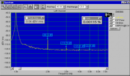
Bateman's published THD (calculated by Spectra 232Plus software): 0.00115%

...................dist.............distortion ......1937 n/2......dist. factor....1950 n^2)/4....dist. factor
# ........... attenuation..... factor raw ... multiplier...weighted '37......multiplier......weighted '50....
H2: ...... -99.12dB ...... 0.0011066% ...... x 1 ...... 0.0011066%...........x1...........0.0011066%
H3: ......-116.78dB ......0.0001449% ......x 1.5 .... 0.0002174%.........x2.25.........0.0003260%
H4: ......-123.81dB ......0.0000645% .......x 2 .......0.0001290%...........x4...........0.0002580%
H5: ......-122.91dB ......0.0000715% ......x 2.5..... 0.0001788%.........x6.25.........0.0004469%
summed THD: .............0.0013875% ...................0.0016318%........................0.0021375%
...............................(1.21x published) .............(1.42x published)................(1.85x published)
--------------------
SUM TEST 2
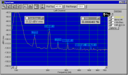
Bateman's published THD (calculated by Spectra 232Plus software): 0.00840%

Not showing my work this time. Too hard to format!
My raw summed THD: 0.0089356% (1.06x published)
Pretty close match this time…yay! I feel confident that Spectra uses no weighting scheme. I still can't figure out why I don't hit it right on the money.
------------------------------------------------------------------------------------------------------------
------------------------------------------------------------------------------------------------------------
SUM TEST 3
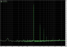
X's published THD (calculated by Rightmark RMAA software): 0.05%

raw attenuation and distortion factor
H2: -69dB 0.0354813%
H3: -84dB 0.0063096%
H4: -109dB 0.0003548%
H5: -118dB 0.0001259%
H8: -110db 0.0003162%
summed THD: 0.042588% (0.85x published)
This discrepancy is very likely due to my imprecise reading of the FFT. Those skinny peaks are hard to eyeball. I guess that RMAA does not indicate exact individual harmonic levels on the graph like Spectra does. Or maybe it DOES use the 1937 weighting scheme!! Yeah right...I just can't read the values.
My attempts to manually sum individual harmonics values from Bateman's graphs into THD have all so far yielded THD figures somewhat close to the ones Bateman published, but mine are oddly all a bit too high. If I use these weighting schemes, I get WAY higher THD sums that are even further off the mark. But for fun, I calculated THD all three ways, to see what the differences would be.
SUM TEST 1
Bateman's published THD (calculated by Spectra 232Plus software): 0.00115%
...................dist.............distortion ......1937 n/2......dist. factor....1950 n^2)/4....dist. factor
# ........... attenuation..... factor raw ... multiplier...weighted '37......multiplier......weighted '50....
H2: ...... -99.12dB ...... 0.0011066% ...... x 1 ...... 0.0011066%...........x1...........0.0011066%
H3: ......-116.78dB ......0.0001449% ......x 1.5 .... 0.0002174%.........x2.25.........0.0003260%
H4: ......-123.81dB ......0.0000645% .......x 2 .......0.0001290%...........x4...........0.0002580%
H5: ......-122.91dB ......0.0000715% ......x 2.5..... 0.0001788%.........x6.25.........0.0004469%
summed THD: .............0.0013875% ...................0.0016318%........................0.0021375%
...............................(1.21x published) .............(1.42x published)................(1.85x published)
--------------------
SUM TEST 2
Bateman's published THD (calculated by Spectra 232Plus software): 0.00840%
Not showing my work this time. Too hard to format!
My raw summed THD: 0.0089356% (1.06x published)
Pretty close match this time…yay! I feel confident that Spectra uses no weighting scheme. I still can't figure out why I don't hit it right on the money.
------------------------------------------------------------------------------------------------------------
------------------------------------------------------------------------------------------------------------
SUM TEST 3
X's published THD (calculated by Rightmark RMAA software): 0.05%
raw attenuation and distortion factor
H2: -69dB 0.0354813%
H3: -84dB 0.0063096%
H4: -109dB 0.0003548%
H5: -118dB 0.0001259%
H8: -110db 0.0003162%
summed THD: 0.042588% (0.85x published)
This discrepancy is very likely due to my imprecise reading of the FFT. Those skinny peaks are hard to eyeball. I guess that RMAA does not indicate exact individual harmonic levels on the graph like Spectra does. Or maybe it DOES use the 1937 weighting scheme!! Yeah right...I just can't read the values.
Attachments
Last edited:
True. I have seen this explanation aswell and from the technical point of view it might make sense. But shouldn't it be possible to measure this effect by the shown procedure? BG might be a good candidate because some people say it changes it Sound very crucial over time....Agree. I've always heard that caps "deform" over time, and that really old parts may need time to "reform", if they do so at all. Unknown to me are the chemical reactions that cause "forming and "deforming", and X's idea is the best one I've heard to date.
Btw. Once i measured the capacitance of brand new Muse KZ (cant remember them around 2000uF/63v?) with some arduino rig. It was a logged loop of charge and slow discharge (5v?)... It took around 20-30 cycels to get them near spec values(before~+100%)... Very interessting... But in real applications this is achieved within a few seconds maybe minutes. (p.s. Used KZ of the same type where immidiatly in the spec range)
Last edited:
Stellar,
While surfing today I ended up on Samuel Groner's website. Appears he has a recent article in Linear Audio which describes a tool for measuring cap distortion and also his measurements. Can be found here, a few entries down, under this heading:
Quadrature Bridge Measures Harmonic Distortion in Capacitors
Analog Circuit Design · Samuel Groner · Publications
More cap measurements?!?
Thanks. I enjoyed the Pass article too.
sure
Not saying I understood it all...even his simplest circuit diagrams are beyond me. But I gleaned a few good tidbits. Seeing the way negative feedback affects harmonic profile on FFT was very helpful. I was especially intrigued by Pass's assertion that less complex music sounds especially great through amps with predominant H2. I must agree...jazz sounds absolutely heavenly from my pocket class A!
But I gleaned a few good tidbits.
And I also. I don't want to believe in $20 jfets, $200 capacitors, or Bybee pixie dust. I do want to believe that it's about finding the sweet spot for the chosen component more than anything else. Using S. Groner's simple circuit, one MOSFET as source follower, I have found that changing the bias current changes the sound. Maybe as X says more current is more distortion, maybe it changes the linearity of the device, but whatever the reason my ears say it is so. The rate at which I am trying new things has dropped significantly since this thread started, but only because I am now experimenting more with what I have. This thread has morphed from topic to topic, and is now seemingly unrelated to it's banner, but I've gained something from it.
Actually higher bias current usually means lower distortion. But higher current draw by load for given bias current usually means higher distortion.
A Russian site recently published a slew of measurement data for the portable DAP I use. I'm confounded by the fact that distortion from the headphone output is proportional to load impedance. To illustrate, here is distortion with a 62 ohm load:
An externally hosted image should be here but it was not working when we last tested it.
Versus distortion with a 300 ohm load:
An externally hosted image should be here but it was not working when we last tested it.
Why should this be? And is this effect common for amps? The THD levels are tiny in both cases, but I'm still curious.
(BTW, I can now recognize the obvious effects of negative feedback on the harmonic profile, thanks to the Pass article
)I saw this in my sims actually. It's true to a point but when you drive the output to higher voltage levels, the higher impedance case is lower in distortion than the low case. And when the impedance goes too low (like 8ohms), it will be worse. So it's not linear by any means. But for averaging listening levels - 125ohms is better than 250ohms. Which is sort of why I have a 270R load resistor as standard. It ensures that you have at least 270R even when nothing is plugged in and this helps to keep the amp stable. But it also gives you an approximate 120ohm load when plugging in 250ohm cans. When plugging in 60ohm cans it is a minor difference.
I saw this in my sims actually. It's true to a point but when you drive the output to higher voltage levels, the higher impedance case is lower in distortion than the low case. And when the impedance goes too low (like 8ohms), it will be worse. So it's not linear by any means. But for averaging listening levels - 125ohms is better than 250ohms. Which is sort of why I have a 270R load resistor as standard. It ensures that you have at least 270R even when nothing is plugged in and this helps to keep the amp stable. But it also gives you an approximate 120ohm load when plugging in 250ohm cans. When plugging in 60ohm cans it is a minor difference.
Makes sense. In the measurements I linked, the DAP produced much higher THD when unloaded than in any other scenario. I can see from the PCA schematic that RL is in parallel with the headphone load at the output.
Using this handy calculator for parallel resistance I can see how 250R cans and 270R RL create the ideal 120R load.
For a minute there I thought I'd be able to sub a higher value resistor for RL to match my 50 ohm cans and hit the same 120R sweet spot. But it's hopeless because of the way they sum. Stock 270R value gives 42R total. Even if I bump up to 100K, I only hit 50R total.
X, would you still recommend I use stock value? Any side-effects to consider with a swap? Worth worrying about?
I'm confounded by the fact that distortion from the headphone output is proportional to load impedance... Why should this be? And is this effect common for amps?
You are probably seeing another limitation of amplifier output capability due to the supply voltage. Many digital audio players run on rather low voltage, so will exhibit higher distortion into high-impedance loads (or unloaded) because the required output voltage may be near the voltage rails. This can be particularly problematic with FET amplifiers, since the capacitance of the FETs is often very nonlinear at low Vds (a condition simulated by the high ratio of output voltage to supply voltage). Check out a MOSFET datasheet for an example.
Makes sense. In the measurements I linked, the DAP produced much higher THD when unloaded than in any other scenario. I can see from the PCA schematic that RL is in parallel with the headphone load at the output.
Using this handy calculator for parallel resistance I can see how 250R cans and 270R RL create the ideal 120R load.
For a minute there I thought I'd be able to sub a higher value resistor for RL to match my 50 ohm cans and hit the same 120R sweet spot. But it's hopeless because of the way they sum. Stock 270R value gives 42R total. Even if I bump up to 100K, I only hit 50R total.
X, would you still recommend I use stock value? Any side-effects to consider with a swap? Worth worrying about?
Adding another resistor can only bring the impedance down. 50ohms is a bit below the marginal minimum recommended value of 60ohms. What you need is the tweak your resistors to increase bias and run at a higher rail voltage. Although your 18.2v from those OK brand batteries is pretty much the max already. Try increasing R4 to 68R and see if you can hear a difference in more powerful dynamics.
Thanks. I'll try 68R for R4 in my second build. I must say that the dynamics from my first one are already quite satisfying with my HD598, and noticeably better than my players' built in amp (which runs on a low voltage battery, as Needtubes guessed...just 4.2v). I will also say that I hear a drop in dynamics when I plug in my 32 ohm AKGs K-55 cans. One more reason to jones for the HD600...
Last edited:
Bateman's full Capacitor Sounds CD has been shared on DIYA as of yesterday!
http://www.diyaudio.com/forums/equipment-tools/306571-cyril-bateman-standalone-thd.html#post5055862
http://www.diyaudio.com/forums/equipment-tools/306571-cyril-bateman-standalone-thd.html#post5055862
So Bateman's rig shows C0G caps as having lower distortion than film caps? I have always used C0G caps on the sensitive Miller compensation duties on legs of transistors. But these are the 10pF to 47pF variety. Tough to get a 1uF C0G radial isn't it? I see it in SMT though. That would make for a very compact board.
- Home
- Amplifiers
- Headphone Systems
- BF862 based SE Class A Headamp without the HEAT