Hi everyone !
I have designed the attached schematic in NI multisim. Everything works brilliant on the simulation software.
I have done a test pcb as well and built the amplifier. After some errors repaired (reversed cap, reversed diode - was my mistake) I have managed to have the amp playing music.
Anyway, something is wrong on the BIAS adjust section. I can't adjust the BIAS from the trimmer although in the simulation it works perfectly.
With no load connected to the output, when powering up I get around 50mA current for 20-40 sec and after that the current goes to 0.35Amp constant.
With the load connected to the output, it draws 0.35Amp.
Can you please help ?
Kind regards,
Julian
Attachments

Yes, I did. Everything is fine. I have used 1% tolerance resistors as well.Have you checked the components around--BD139 ?
I was wondering if there's anything to do with the CE capacitor value of BD139. Couldn't find any specific info online.
I was thinking about that. Might sound silly but how can you test that ? Decoupling caps on the CB predrivers ?Are you sure the amplifier isn't oscillating?
Regards
Is the T31 (BD139) mounted on the heatsink of the output transistors?
Yes, it is.
Is T29/30 current a limiting circuit? If so it looks like it will work backwards.
T25,T28,T29,T30 - short circuit protection (out to GND).
In the simulation, it works fine even with 2ohm load.
Can you please suggest changes to this ? 🙂
Last edited:
100pf were added to C-B of T32, T33. Now it draws 160mA on idle. Volt drop on 0.33 resistors is 0mV (which I know is wrong).
Will try to go lower with 100pf caps.
Will try to go lower with 100pf caps.
I'm just looking at how it's connected. If voltage at R76 / T36 junction rises, voltage to the base of T29 will rise causing voltage to the base of T25 to go negative, increasing collector current through T25, raising drive current to the output stage. I think this is backwards to what you want. Maybe this is becoming partially active as it warms up?
Quote- "but how can you test that "-- I take it you don't have a scope ?
In that case have you a sensitive AC millivoltmeter ?
Not the low volts on a digital multi meter which is useless for accurate HF measurement due to low bandwidth and RF pick up which I found early on in life when I worked in telecommunications.
But a genuine AC millivoltmeter of high bandwidth .
This will show up oscillations if a scope is not available.
If not just use your digital meter on AC but be prepared for a highly inaccurate reading --in other words it will just give a rough indication or if severely bandwidth-limited no indication .
Many thanks to all of you gentlemen.
I have increased to 220pf the caps on T32, T33 and I have 40mA now on idle. It stays cold, no worries.
So, it was oscillating initially.
Still can't adjust the BIAS. Vdrop on 0.33R resistors is 1.2mV.
If I'm not wrong it should be around 2.5mV. Should I consider changing values of R65/R64 ?
It plays clear after 2.5mV is reached on emitter resistors.
Regards
Should I consider changing values of R65/R64 ?
Yes but not by a wide margin slowly does it .
Are you sure the semi-variable resistor has its FULL resistance travel ?
Yes but not by a wide margin slowly does it .
Are you sure the semi-variable resistor has its FULL resistance travel ?
Should I consider changing values of R65/R64 ?
Yes but not by a wide margin slowly does it .
Are you sure the semi-variable resistor has its FULL resistance travel ?
Will try to do that in multisim first.
About the trimmer, I have just checked: it goes from 0 to 978ohm which I suppose is good enough.

I was thinking about that. Might sound silly but how can you test that ? Decoupling caps on the CB predrivers ?
Check if the resistor in the Zobel network is heating up, if it is, then there's oscillation.
I'd probably suggest starting by increasing the VAS compensation. 10pF is going to be too small. Try 100pF and then go down from there.
One thing you can try in your sim is feeding in a square wave, bypass DC blocking capacitors when you do this. If you see any ringing on the edges of the square wave, that's a problem
@jwilhelm Thank you for your suggestion. Will do that.
@jaycee The resistor in the Zobel network isn't heating up. It works now, still have to put it on a scope.
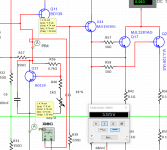
Regarding the BIAS problem, in the simulator I have measured Vce and I across T31 and I have got results as in the attached photo.
On the test pcb I have measured Vce 1.36V for the same T31.
Something is not right. 🙂
@jaycee The resistor in the Zobel network isn't heating up. It works now, still have to put it on a scope.
Regarding the BIAS problem, in the simulator I have measured Vce and I across T31 and I have got results as in the attached photo.
On the test pcb I have measured Vce 1.36V for the same T31.
Something is not right. 🙂
Attachments
Can you give me a reason why you have a BD139 in this position ?
It requires a good bit of current to achieve a small hfe.
Most of the JLH/D.Self designs use a 100ma BJT ,your current through it shows just under 5ma ,something like a BC548 etc would be more appropriate and be more controllable.
If I am missing something here please elaborate ?
It requires a good bit of current to achieve a small hfe.
Most of the JLH/D.Self designs use a 100ma BJT ,your current through it shows just under 5ma ,something like a BC548 etc would be more appropriate and be more controllable.
If I am missing something here please elaborate ?
That would need to be either a layout issue on your board or shorted / incorrect devices. T31 should see enough voltage to overcome 6 PN junctions or roughly 3.6V.
- Home
- Amplifiers
- Solid State
- BIAS setting problem on amplifier