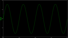
Something wrong, maybe simulator have bad transistor models. With so high values of R6 and R7 i doubt if output transistors would be able to output full current to load. Without load or without signal applied idle current may look ok in sim. Did you tried simulate with signal and look at output voltage swing ?
Thanks, I suspected something was wrong.
Now I've come full circle - the best base-emitter measurement I can get is with 1K resistors - 425mV.
With one biasing diode Q current is 40mA; Re (0.33) are 15.2 + 16.4 mV unadjusted. I'm still reading up on using Spice!
Now I've come full circle - the best base-emitter measurement I can get is with 1K resistors - 425mV.
With one biasing diode Q current is 40mA; Re (0.33) are 15.2 + 16.4 mV unadjusted. I'm still reading up on using Spice!
Attachments
Last edited:
What I learned:
With a single diode the current was too low. With two the current was too high using Re 0.33.
Swapping 0.33 for 7.5 ohm the quiescent current drops to below just 50mA and Voltage at Ib (Q1) is now 710mV. THD is 0.04. Thanks for the previous tips. Possibly this is a candidate for the breadboard live test Comments welcome.
Emitter resistance should not be so high , maybe 0,5-1 at maximum. It would dissipate power, which would get your speaker otherwise. Did you tried another type diodes? Let's say one 1n4148 and one 1n5818 in series? Or 1n4007 two in series?
In one of my projects earlier I've had such biasing problem, and solution was non standard - tlvh431 ic, adjustable shunt regulator, which was able to provide smaller voltage drop than two diodes, and with potemtiometer i was able to adjust to idle current i needed.
In one of my projects earlier I've had such biasing problem, and solution was non standard - tlvh431 ic, adjustable shunt regulator, which was able to provide smaller voltage drop than two diodes, and with potemtiometer i was able to adjust to idle current i needed.
Thanks, I'll look for a Spice model to give it a go.tlvh431
Let me post what I've found worked best in Spice simulation.Let's say one 1n4148 and one 1n5818 in series? Or 1n4007 two in series?
Two MURS160 diodes between two 20K and Re 1 ohm each; 496mV base to emitter; quiescent 50mA.
With 57Ks and 1n4007s got same measurements but trimming is not as smooth.
To get higher base-emitter voltage is difficult with my driver-less op-amp driven design. My hunch is 496mV base-emitter will enough. Comments welcome.
Decrease these resistor base-emitter resistors first, as you will not get high power output , they will limit base current .
Also you can try to play more with vbe multiplier. Use 1k base-collector resistor and 47k base-emitter. If quiescent current will be too small, decrease 47k . This way temperature stability can be preserved, just mount transistor on same heatsink as output transistors.As example use one of bd135-bd139 series transistors, for pnp just reverse polarity, keeping lower value resistor at base-collector. As you don't use driver transistors, normally used in vbe multiplier resistor values will not suit there, so just play in sim, but keep in mind, that real transistors differs much from spice models.
Also you can try to play more with vbe multiplier. Use 1k base-collector resistor and 47k base-emitter. If quiescent current will be too small, decrease 47k . This way temperature stability can be preserved, just mount transistor on same heatsink as output transistors.As example use one of bd135-bd139 series transistors, for pnp just reverse polarity, keeping lower value resistor at base-collector. As you don't use driver transistors, normally used in vbe multiplier resistor values will not suit there, so just play in sim, but keep in mind, that real transistors differs much from spice models.
That's pretty much what I've been doing this past week and failed to get close to what I thought reasonable. I'm going to abandon this op-amp driven design. I sure have learned from your posts though, arigato!Decrease these resistor base-emitter resistors first, as you will not get high power output , they will limit base current .
Also you can try to play more with vbe multiplier. Use 1k base-collector resistor and 47k base-emitter. If quiescent current will be too small, decrease 47k . This way temperature stability can be preserved, just mount transistor on same heatsink as output transistors.As example use one of bd135-bd139 series transistors, for pnp just reverse polarity, keeping lower value resistor at base-collector. As you don't use driver transistors, normally used in vbe multiplier resistor values will not suit there, so just play in sim, but keep in mind, that real transistors differs much from spice models.
I'm using Qspice but isn't it just a new interface over the underlying Spice made years ago. I think my design the bottleneck.Why not to try different simulator?
I know where to look for these models. This project is to come up with something simple and low cost for a local Men's Shed SIG. My proposed ones are cheap and have high hFE and fT which I read would be useful.Do you have another complementary power transistors in simulator library? Like 2sc5200/2sa1943 , bd138/bd139 etc?
You mean base-emitter voltage? It comes automatically, when some current flows between base-emitter junction, it acts like diode and have some forward voltage. Important is not this voltage drop, but base current, which is amplified by transistor hfe times . 1ma base current x 100hfe = 100ma collector current. What voltage drop has base-emitter at this condition, is not much important, it should not be a target. Or maybe you mean some other voltage?
Agh, I should measure Ib (Q1) not bother abt mVWhat voltage drop has base-emitter at this condition, is not much important, it should not be a target.
Let me absorb what you've explained. I really appreciate the time you've spent answering.. Again, thanks.
I've been stuffing my circuit with endless diode permutations and measuring mV and mA blah - jeez, the variation is incredible. Depending on the diode types, measurements go up and down like ******' drawers on sailors day! I learned a lot. My limited knowledge tells me that if current starved then output Watts will be low. Is selecting the diode mix that gives me the highest mA at base-emitter the right move?What voltage drop has base-emitter at this condition, is not much important, it should not be a target.
Currently with MURS160 + 1N5400: 50mV for Q current with Re 1ohm; Ib (Q1) 500mV and 320mA. Comments welcome.
Attachments
Thanks, I didn't explain well enough, sorry. 320ma Ib is the current to base. Previously post suggested emitter-base should be over 0.5mV.This idle current , determined by diodes, does not affect possible output power to speaker.
What you've mean with 320ma Ib Q1? Base current can't be so much higher than idle current of emitter.
With the various diode permutations mA goes between 190 - 350 mA. I wanted to know if this taking this measurement can give me information to determine which diode to choose.
I know to adjust quiescent current to the designer's instructions when I'm assembling a kit amp. Now that I'm trying to design one I need to know how to determine that quiescent current.
Quiescent current value is chosen by minimum distortions, but taking into account, that it should be just enough . In practical.amplifier, you should supply some signal to input, check output with oscilloscope, and watch for crossover distortions, when sine wave is crossing zer r use distortions metering tool and check actual distortion at variuos idle current values. If increased idle current don't decrease distortions, don't increase ir, it will just waste energy, for which you will pay every month and increase hearsink temperature, also amplifier would be more prone to failures, because of transistors dissipated power being closer to max allowed.
However, there are many class A amplifiers, discussed there .High idle current can decrease distortions of some circuits, simplify those circuits. In practical circuit i would choose current, at which distortions is enough low, and not waste energy to heat. In this circuit , which has negative feedback, i would suggest 20-50ma idle current.
What exactly you've meant with “ 320ma to base “? Resistors in this circuit would not allow such current to appear in base - emitter junction, 36,5k resistor allows just 0,74ma base current.
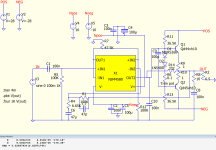
Also another thing i see - opamp is supplied with +-16V , output transistors supplied +-28V . Explanation is that transistors in this connection method can repeat input (base) voltage minus 1v approx , and - vce sat. Opamp output can swing lets say +-14v . At speaker output theoretically you can have just +-13volts maximum. So you safely can use same suplly voltage for both , transistors and opamp. If there would be a gain stage between opamp output and bases , then this limit would not apply.
r use distortions metering tool and check actual distortion at variuos idle current values. If increased idle current don't decrease distortions, don't increase ir, it will just waste energy, for which you will pay every month and increase hearsink temperature, also amplifier would be more prone to failures, because of transistors dissipated power being closer to max allowed.However, there are many class A amplifiers, discussed there .High idle current can decrease distortions of some circuits, simplify those circuits. In practical circuit i would choose current, at which distortions is enough low, and not waste energy to heat. In this circuit , which has negative feedback, i would suggest 20-50ma idle current.
What exactly you've meant with “ 320ma to base “? Resistors in this circuit would not allow such current to appear in base - emitter junction, 36,5k resistor allows just 0,74ma base current.
Also another thing i see - opamp is supplied with +-16V , output transistors supplied +-28V . Explanation is that transistors in this connection method can repeat input (base) voltage minus 1v approx , and - vce sat. Opamp output can swing lets say +-14v . At speaker output theoretically you can have just +-13volts maximum. So you safely can use same suplly voltage for both , transistors and opamp. If there would be a gain stage between opamp output and bases , then this limit would not apply.
- Home
- Amplifiers
- Solid State
- Biasing target for push-pull amp