it is well engineered DAC, and quite good sonicaly (same level as Ayre qb-9 and better than hegel hd25) but I am looking for more interesting IV stage , something like this-
2x ess9018 dac(very poor power suply, but IV can be promising - not usual text book OPA design with es9018)
2x ess9018 dac(very poor power suply, but IV can be promising - not usual text book OPA design with es9018)
Attachments


Yeah, that one is definitely a transimpedance amp and looks interesting. Not familiar with those transistors though.
I think we(I) have lost completely. at first i thougth a good idea for sound i search is very simple iv and many dac chips. Now that is can not be done(with pcm 63p-y) I can
1) buy 40-50psc(just in case to be on safe side) of pcm 63p-k (maybe they are pcm63p-j ,just relabeled in china) and try simple resitor or transformer output.
2)design dac with 8-16 psc pcm63p-y with some interesting powerfull active IV stage
its very hard when desire to built is much deeper than knowledge to do so.
Why draw a schematic with the negative rail on the top? Just to make it harder to read.
The I/V resistors are referenced to the negative rail I believe, and after those you have a opamp-like discrete circuit. But I´m no expert to comment any further.
The boards you have shown have mostly small to-92 transistors, which are unsuitable for many paralleled dacs. You want big transistors and high bias current!
wel I belive,one of my dac's with 2x pcm1794A have "current steering IV" technology. is this we are talking about?-
By the way, prior to posting here and asking for help I searched for few month any interesting dac with pcm 63 or pcm 1702/ 1704 which can be replaced with pcm63, and found basicaly nothing except this one in japaneese- http://easyaudiokit.hobby-web.net/kit-room2/DACManual/DAC63-4SManual.pdf which output stage is far away with what i consider (with my very limited knowledge) as exotic. I would gladly repeat someones project , but there is no such projects on the net.. So here is my only hope.
Prehaps a description of my current project will inspire you. I started from the same place you are now. I knew little about highend DAC design but I was willing to learn and produce an original design.
Planned features:
* 64 PCM1704K wired in parallel or as differential pairs.
* PC interface is bulk transfer USB.
* Supports sample rates up to 768K.
* All clocks come from a local oscillator.
* Four layer PCBs with components on both sides.
* Black Gates, where appropriate.
* Clock distribution uses low-skew, low-jitter clock drivers.
* Complementary clocks preserve the clock/data phase relationship.
* Optional linear interpolation ratio is 4x, 8x, 16x or 32x.
* I/V resistors are short lengths of 42µ, 6N magnet wire.
* Individual power supplies for clocks, logic, USB, and left/right channel DAC chips.
* All wire interconnections pass through ferrite cores.
* Companion player resamples and optionally applies sinc or sinc-squared compensation.
* Audio file metadata is used to select sample rate, interpolation and reconstruction filter.
The schematic you have posted is good, I have not looked into the circuit operating points but the transistors are ok. They can handle a much higher quiescent current than your jfet i/v.
http://www.fairchildsemi.com/ds/KS/KSA1220A.pdf
http://www.fairchildsemi.com/ds/KS/KSA1220A.pdf
Prehaps a description of my current project will inspire you .
You do not need to inspire drawning man for get out of the watter 🙂 In what stage is your project? if you have pcb files which I can adapt to pcm63dac(which is not easy, much easier to adapt pcm 1704 to pcm63 because size of the package) and if pcm63 will work in this schematics I am in for completely folow your design. I can donate to you and for diyaudio for that, amen 🙂
The circuit for PCM1794 might need some changes to work with pcm63, but it looks like a good circuit.
(How ironic, a "fet audio" circuit that is all-bjt!🙂)
(How ironic, a "fet audio" circuit that is all-bjt!🙂)
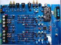
OK , while we waiiting tam Lin answer I have just bought a new full discrete IV 2x es9018 dac PCB in picture above, for very reasonable price (arround 1K USD to doors) will see how it will sound..
I just realized that I have no less than 14 DAC in my home and studio(hope my wife does not read that) But I will trade ALL of them to ONE much better maybe with help of members my dream come true..
I just realized that I have no less than 14 DAC in my home and studio(hope my wife does not read that) But I will trade ALL of them to ONE much better maybe with help of members my dream come true..
You do not need to inspire drawning man for get out of the watter 🙂 In what stage is your project? if you have pcb files which I can adapt to pcm63dac(which is not easy, much easier to adapt pcm 1704 to pcm63 because size of the package) and if pcm63 will work in this schematics I am in for completely folow your design. I can donate to you and for diyaudio for that, amen 🙂
Originally, the design used S/PDIF input and I was ready to order PCBs when I decided to switch to USB. Now I have to finish the PCB layout for the circuits that interface with USB, write the firmware and driver software. No small task. Then we shall see. I doubt my PCB files would be any use to you because I use non-standard design software I write for myself. Besides, the whole idea of DIY is Do It Yourself.
This looks like a good passive I/V - it´s not just a resistor, it´s an I/V network:
http://members.chello.nl/~m.heijligers/DAChtml/dig_r2b.pdf
Any opinions?
I had a quick look - its using CLC filtering on the output, a definite step up from cap to ground as used by many. It doesn't look as though much attention has been paid to power supplies though - they use separate analog and digital regs even though TI/BB DS for the PCM63 says there's no advantage in doing so. They use standard regs so I would guess the sound will be average but its impossible to tell without seeing how its laid out.
Sounds like a lot of work Tam Lin!
I´m looking to implement a dsp crossover on fpga. But I always start simple.
(You´re brave, no way I would attempt 64 paralleled dacs as a first project!)
I´m looking to implement a dsp crossover on fpga. But I always start simple.
(You´re brave, no way I would attempt 64 paralleled dacs as a first project!)
Now I have to finish the PCB layout for the circuits that interface with USB, write the firmware and driver software. No small task. Then we shall see. I doubt my PCB files would be any use to you because I use non-standard design software I write for myself. Besides, the whole idea of DIY is Do It Yourself.
I have to simulate these filters to answer a question that arised... CLC vs. LCL
Seems to me that LCL is better, because it stops some of the HF current from circulating in the first place (instead of shunting it to ground like in CLC)
But I could be wrong
Seems to me that LCL is better, because it stops some of the HF current from circulating in the first place (instead of shunting it to ground like in CLC)
But I could be wrong
I had a quick look - its using CLC filtering on the output, a definite step up from cap to ground as used by many.
I also agree that the cap on the output of a DAC (or current source) is a bad thing so will always use an L as the first element. I've found with a discrete I/V (a common-base transistor) it tends to go unstable when feeding a cap from its collector. A series L fixes up this problem.
Hello everyone, I still searching info from internet , but still find nothing interesting. Its not one day project or short desire, so i will wait for any of the members (with similar plans) project details.
After lot of reading(more and more understand that paraleling DAC subjectively gives to people what i seek in dac- dynamyc slam, soundstage) I finaly decided to act- better slight less worse DAC than.. none dac!!
So decided to make old school and modular contruction of this dac (with some boards can be skipped or changed) I choose it basicaly for experiments and diferent power supply requirements
1)USB Digital input Board x1
2)Oversampling Board x1
3) DAC board x1 (stackable version) there will be 4 chips per phase or 8 (if stacked on top second board) configurable for SE or Balanced configuration
4)Analog output board x3 ( either transformer or two transitor versions)
5)Digital supply board for Digital input Board
6)Digital supply board for Oversampling Board
7)Digital suply for digital section of PCM63
8)Analog supply for analog section of PCM
9)Analog supply for transistor output section
Placement space requirements is 430 widht with 140-150mm height and 350-450mm depth with no more than 25kg of weight(for easy of transportation)
Folowing questions technical questions-
1) is it make sense separate electricaly isolate digital intput board from oversampling or from dac board or both ? Or if its worht to isolate pcm 63 from sm 5842? I have read that in this exact pair sm5842+pcm63 isolating will give more trouble than benefit.
2)is it make sense to make separate (or some lets say analog pcm 63 or analog output )power supply for each channel?
3)I supose transfer power supply (transformer, regulators) outside of dac board is not good idea?
4) 2 or 4 layers boards on digital boards?
5)make registers shift that sm5842 and pcm 63 will understood i2s format
6) and last but not least will make it simple paralel chip dac or "shifted" - I recently was in quests with former LessLoss digital enginier, and he showed and drawed me his own pcm1704k dac where he used 2 chips per channel, but not paraleled , just second chip get delayed signal and make digital steps smaller.
Now Details questions selecting main components. I love very large holographic 3d soundstage, and very airy (not rounded,or rolled off ) high frequency extension when hight are very transparent and airy but in natural way ,not piercing ear hi-fi ticking sound. Transparency in my words if transfer to speaker woulf make this frequency response where black is neutral dac, blue so called transparent modern hi-fi dac, and red my preferable dac. those kind of dac even on bookshelf speakers sound like a big floorstander.I belive this picture will be perfectly clear for speaker designers. as a bonus I still ahve a problem-in my forties I still can hear 17kHz on speakers (not headphones) and what is even more worse value HF range from 14 and up very much. At free time I do cd records corection and even if mp3 128bit record(cuted hights from ~15khz) lifted with software 15-17khz by +6-7db I perceive it as "freshenss" in sound (even if there is no music here on mp3) same goes for waw records, some engineers just do no think about this region and its sometimes rolled off..
Attachments

Last edited:
As you understood I do not look for high resolution honest neutral DAC (I have few of them) The dynamyc and bass should be very powerfull. I was tend to forgive recessed midrange but over years I started to enjoy more forward)or better projected) midrange (however very few electronic I heard can do upfront mids and still maintain large deep scale of soundstage) All dac I have heard /have with PCM63 have slight wooly and soft sound, with slight loss of edge and sharpness of soundstage images. So by no means I want use components with makes sound wooly and soft but those who gives best soundstage, ant transparency. Why I choose pcm63? because it by itself have "weight" on instruments, and bass. So questions,considering my sonic taste-
7) Which regulators? what configuration/schemtic for digital, analog and transitor suplies? or better go discrete like http://www.teddypardo.com/resources/superteddyreg.html
8) Which caps with regulators, and is it any benefit from shunting electrolytes with MKP or maybe in some powersuplies I can make capacistance only from MKP. I love Vishay MKP particular series models. sonic. from electroyltes I have decided to go with simple panasonic FM
I have not decided to use Black gates non polar caps in this project. while they sound beautifull and impressive ( big rounded bass, darkness in soundstage) I do not like that after longer period my amps will need to play non stop for 2 days to return to sound amp was tuned. Also I feel that black gates is better with es9018 than with pcm63. Diyers,please expect around 400psc of genue Black gates N be posted here on Dyaudio after this dac will be completed 🙂
8) which caps in pcm63 legs? I am thinking of 200uf for o,15uf caps sonicaly silver mica would be fine, but size is not tolerable, also pickup of noise(?) is Wima FK good choise.
9) what about oscons in digital section? any other alternatives?
I would be gratefull for any answer to any question of this thoughts..
Last edited:
More to add.
In my view, there can be no such thing as an NOS bitstream dac, regarding your PCM1794 comment. The d-s modulator is an oversampler itself, with an OS d.f. merely adding more OS. If you look at a sinewave output from an "NOS" PCM1794 versus the same from a ladder dac, it's pretty obvious one has little relationship to the other. Also, the d.f. within the PCM1794/etc. chips seems known to be markedly inferior to good d.f. chips like the DF1704 and SM5847.
I certainly agree with you on the sound of a stock or "conventionally upgraded" Accuphase DC-91. For god knows what reason, other than it was common practice at the time, each of the 32 pcm63 chips has it's own feedback i/v opamp, then into a common buffer, then into a HORRIBLE GIC filter, then output buffer and balanced driver amp. With single common passive i/v resistor per 16 dacs per channel, then my no-feedback voltage gain + line driver stages, plus way larger caps around each of the dacs(over 500 nice Nichicon caps I had to replace with larger nice Nichicon caps, exhausting), the resulting sound is absolutely spectacular, without even changing the ancient YM3436 input receiver or d/f arrangement.
Probably using Burr Browns linear phase GIC from their application notes. Here is a perfect example of something that you could have spent a bucket load of money compromised by the use of op-amps. Never could it compete with a PCM63 single DAC per channel discrete and/or tube designs. Forever compromised by the use of op-amps. What a waste of good PCM63s. Just goes to show that most stuff sells on marketing and not on sound.

- Home
- Source & Line
- Digital Line Level
- Calling DAC experts for ultimate PCM63 DAC