Joseph K said:With the trimmer set to ~13pF [max.], I got this picture:
So, it seems that hte ugliest part was due to the scope ground lead, but still, it seems to me that the Qout is extremely sensitive to the load capacitance present.
asymmetrtical output impedance - anyone care to explain ?
Finally, I would like to ask pardon from Elso for being unfoundidly obtrusive...
Franz, based on the things previously told, the divider might not be the good solution. But, I see that You had just partially re-configurated your circuit: it is still AC-coupled! Which means it shifts down the input signal to be at around zero, and so continuously exceed the negative signal input limit.. Not a good sign. I would use the simple DC coupling seen on Elso's diagram.
Ciao, George
Attachments
Joseph K said:Finally, I would like to ask pardon from Elso for being unfoundidly obtrusive...
Ciao, George
Hi George,
No problem at all! Feel free to experiment with the circuit as it is no secret.
Maybe this:
http://www.hagtech.com/hagclock.html
can give you some inspiration too.
I experienced also problems measuring the square wave. It sounds all too familiar to me.
Ciao,
")
Ad8611
Hi George, Don't use the AD8611. It sounds BAD even in a 45.1584MHz clock! The wave form is somewhat comparator dependent. The MAX913 has a slightly different picture from the AD8561 but sounds almost the same.
Joseph K said:output of ad8611:
Hi George, Don't use the AD8611. It sounds BAD even in a 45.1584MHz clock! The wave form is somewhat comparator dependent. The MAX913 has a slightly different picture from the AD8561 but sounds almost the same.
Thanks, Elso!
The Hagtech circuit is interesting...
Given that we are talking about it.. Guido, when inadvertently disclosed some little information about your circuit, then yes, helped You from one point of view, and that's baad.. But helped also us, happy or what users.. . And that's good... Thanks, Guido!
Now, could we get to work? I don't think it's nice to expect more info from him, but it's still possible to think aloud? When he said 1/F noise, that possibly can mean only one thing: active devices. Now, I tried to look for the 1/F noise corner of the J309, no success. But, it's a very low noise [RF vise, 100 MHz] device.. SO, probably yes, it's more noisy than a good low noise BJT, but still not prohibitively so..
So, if not him, what else? Uhm, one culprit I could imagine: The TL431. And your pass transistor config does not provide any low frequency filtering.
I understand that you like the sound this way better, but if they show up in the measurement, maybe it would worth it to search further, as Kuei would say, until one satisfies both the scope and the ear..
Ciao, George
The Hagtech circuit is interesting...
Given that we are talking about it.. Guido, when inadvertently disclosed some little information about your circuit, then yes, helped You from one point of view, and that's baad.. But helped also us, happy or what users..
. And that's good... Thanks, Guido! Now, could we get to work? I don't think it's nice to expect more info from him, but it's still possible to think aloud? When he said 1/F noise, that possibly can mean only one thing: active devices. Now, I tried to look for the 1/F noise corner of the J309, no success. But, it's a very low noise [RF vise, 100 MHz] device.. SO, probably yes, it's more noisy than a good low noise BJT, but still not prohibitively so..
So, if not him, what else? Uhm, one culprit I could imagine: The TL431. And your pass transistor config does not provide any low frequency filtering.
I understand that you like the sound this way better, but if they show up in the measurement, maybe it would worth it to search further, as Kuei would say, until one satisfies both the scope and the ear..
Ciao, George
Attachments
Hi George
Many thanks for your measurements and good description!
It is clear for me now, that I have to redesign my two kwak clocks with positive and negative supplies.
Maybe, you find a way to solve this input problem of the comparator, even with single supply?
Maybe, afterwards my comparison with the Tent XO looks different? But this story is a good example, not to experiment with "own" circuits not having adequate measuring skills and equipment.
BTW: for my sake, it was the idea from Elso, to spend the NAD541i a single supply clock
And it was definitely my mistake, not to remove the coupling cap in the circuit.
Franz
Franz,
Don't feel bad, You should always be free to experiment! I think Elso would just say the same. What would be a reasonable tactic is to realize at least one unit of his clock as faithfully as possible - then one could get an impression what was his intention. Then you deviate!
Some afterthoughts about the above measurements: Looking at the graphs in posts 115 /116, I feel like I should quantify the [possible] differences. So I will repeat them, but now doing an FFT.
As regards double supplies, it really resolves this problem, [if exists]. And, as came to my mind later, helps also with respect to ground bounce: the [+IN] is not referred any more to the jumpy ground, but to the - supply.
Though there is also the 100nF filter cap, which happily transfers the bounce backwards... life is difficult..
Then, the ground bounce instead is a problem. What became clear for me is that one should be very careful with the load on the comparator. Reactive loads generate groundbounce. Because the negative going edge is just too fast. Would be better if the comparator would be slower..
And reactive load means the simple, short wire that leads to the main circuit. Not to speak about a multipoint distribution..
There is only one way to make that wire not reactive - a transmission line.
With all it's consequences, that is, signal amplitude loss at termination, and an overall heavy load close to the chip output capabilities..
Or, a buffer right after the comparator, very close to it, and presenting small input capacitance? Then one should decouple also the buffer very well..
Or, the re-sampling flip-flop only a cm away, directly [and uniquely] connected.. This is what in fact I try to do, always.
I think I'm not just imagining all these, these are real problems. But it does not mean that the clock would not work, only not so well as it would be theoretically possible.
Ciao, George
Joseph K said:Franz,
Don't feel bad, You should always be free to experiment! I think Elso would just say the same. What would be a reasonable tactic is to realize at least one unit of his clock as faithfully as possible - then one could get an impression what was his intention. Then you deviate!
Some afterthoughts about the above measurements: Looking at the graphs in posts 115 /116, I feel like I should quantify the [possible] differences. So I will repeat them, but now doing an FFT.
As regards double supplies, it really resolves this problem, [if exists]. And, as came to my mind later, helps also with respect to ground bounce: the [+IN] is not referred any more to the jumpy ground, but to the - supply.
Though there is also the 100nF filter cap, which happily transfers the bounce backwards... life is difficult..
Then, the ground bounce instead is a problem. What became clear for me is that one should be very careful with the load on the comparator. Reactive loads generate groundbounce. Because the negative going edge is just too fast. Would be better if the comparator would be slower..
And reactive load means the simple, short wire that leads to the main circuit. Not to speak about a multipoint distribution..
There is only one way to make that wire not reactive - a transmission line.
With all it's consequences, that is, signal amplitude loss at termination, and an overall heavy load close to the chip output capabilities..
Or, a buffer right after the comparator, very close to it, and presenting small input capacitance? Then one should decouple also the buffer very well..
Or, the re-sampling flip-flop only a cm away, directly [and uniquely] connected.. This is what in fact I try to do, always.
I think I'm not just imagining all these, these are real problems. But it does not mean that the clock would not work, only not so well as it would be theoretically possible.
Ciao, George
Hi,
There are alternatives for the comparator, you may try LT1016.
For reference, one of my clocks measured with 15 cm twisted wire into 50 ohms.
best regards,
Attachments
Lars Clausen said:Guido: Unfortunately at 100k input impedance, the S/N ratio of these comparators start to get very poor, translating directly into jitter.....
Also i don't think you would use one of these for your own clock ??
Hi Lars,
Allthough not explicitely stated, I did not suggest to use LT1016 "only".
At the risk of providing usefull info to the community: one could consider a cascaded circuit to convert sinewaves to square waves.
cheers,
Guido,
Your pic is nice, but before saying Wow, I would like to clarify some details, so as not to compare apples & oranges.
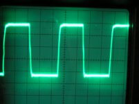
Your vertical division is obviously 1V/div, this is clear. Also is clear that the circuit is some type of cmos, probably HC. [from the amplitude & symmetry] Your horizontal scale is 20 nSec, I suppose. Because if it's true, then one cycle is ~90nsecs, as it should be with a 11,288 MHz clock.
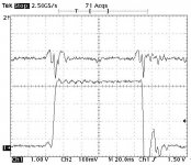
Now, the scale on mine graph is 10nsec /div, the problematic edge is actually, as can be seen by the cursors, 2,4 nsec fall time, conservatively measured. Measured like in the data sheet [20%-80%], it is very close[~1.7nsec] to the data sheet value. This is valid also for the rising edge, that is, it's like the data sheet value[3.8 nsec, or 5nsec, if conservative]. So nothing is wrong with the chip, or setup. [And I would challenge anybody (Bricolo) to reproduce the data sheet values as nice as it is here]
Now, your rising /falling edges are also slightly assymetric, though much less. And they are, at least, and in accordance with the 20 nsec/div time scale, 5nsec, the slower might be even more. So, your output edges, BOTH, look like the rising edge on the Kwak Clock.
And as it can be seen on mine graphs, indeed at this velocity there are no problems showing up, and this is why I said slower might be better here.
The AD8561 is a bipolar device, and as such, it uses some fast TTL like output driver configuration, and as we all know, TTL level signals are indeed assymmetric, not rectangular.
You are right, that other comparators will behave differently, and indeed, the Hagerman clock has a more symmetric output.
But, while looking around about the common-mode input range problem, I have just noticed, that this problem will present itself in a more brutal form with the LT1016, properly because that one is an NPN input pair device, and the strongly positive -going input signal will encounter a much heavier load. So no wonder, that Elso was experiencing a better sound with the AD unit. Or at least this is my hypothesis. Of course, proper signal conditioning would be due.
Lars, I don't really get your comment, the input impedance is high, and properly this is why AD prescribes an appropriate LOW driving source impedance? Which is kept in Elso's circuit.
Ciao, George
Your pic is nice, but before saying Wow, I would like to clarify some details, so as not to compare apples & oranges.
Your vertical division is obviously 1V/div, this is clear. Also is clear that the circuit is some type of cmos, probably HC. [from the amplitude & symmetry] Your horizontal scale is 20 nSec, I suppose. Because if it's true, then one cycle is ~90nsecs, as it should be with a 11,288 MHz clock.
Now, the scale on mine graph is 10nsec /div, the problematic edge is actually, as can be seen by the cursors, 2,4 nsec fall time, conservatively measured. Measured like in the data sheet [20%-80%], it is very close[~1.7nsec] to the data sheet value. This is valid also for the rising edge, that is, it's like the data sheet value[3.8 nsec, or 5nsec, if conservative]. So nothing is wrong with the chip, or setup. [And I would challenge anybody (Bricolo) to reproduce the data sheet values as nice as it is here]
Now, your rising /falling edges are also slightly assymetric, though much less. And they are, at least, and in accordance with the 20 nsec/div time scale, 5nsec, the slower might be even more. So, your output edges, BOTH, look like the rising edge on the Kwak Clock.
And as it can be seen on mine graphs, indeed at this velocity there are no problems showing up, and this is why I said slower might be better here.
The AD8561 is a bipolar device, and as such, it uses some fast TTL like output driver configuration, and as we all know, TTL level signals are indeed assymmetric, not rectangular.
You are right, that other comparators will behave differently, and indeed, the Hagerman clock has a more symmetric output.
But, while looking around about the common-mode input range problem, I have just noticed, that this problem will present itself in a more brutal form with the LT1016, properly because that one is an NPN input pair device, and the strongly positive -going input signal will encounter a much heavier load. So no wonder, that Elso was experiencing a better sound with the AD unit. Or at least this is my hypothesis. Of course, proper signal conditioning would be due.
Lars, I don't really get your comment, the input impedance is high, and properly this is why AD prescribes an appropriate LOW driving source impedance? Which is kept in Elso's circuit.
Ciao, George
Joseph K said:Guido,
Your pic is nice, but before saying Wow, I would like to clarify some details, so as not to compare apples & oranges.
Your vertical division is obviously 1V/div, this is clear. Also is clear that the circuit is some type of cmos, probably HC. [from the amplitude & symmetry] Your horizontal scale is 20 nSec, I suppose. Because if it's true, then one cycle is ~90nsecs, as it should be with a 11,288 MHz clock.
Now, the scale on mine graph is 10nsec /div, the problematic edge is actually, as can be seen by the cursors, 2,4 nsec fall time, conservatively measured. Measured like in the data sheet [20%-80%], it is very close[~1.7nsec] to the data sheet value. This is valid also for the rising edge, that is, it's like the data sheet value[3.8 nsec, or 5nsec, if conservative]. So nothing is wrong with the chip, or setup. [And I would challenge anybody (Bricolo) to reproduce the data sheet values as nice as it is here]
Now, your rising /falling edges are also slightly assymetric, though much less. And they are, at least, and in accordance with the 20 nsec/div time scale, 5nsec, the slower might be even more. So, your output edges, BOTH, look like the rising edge on the Kwak Clock.
And as it can be seen on mine graphs, indeed at this velocity there are no problems showing up, and this is why I said slower might be better here.
The AD8561 is a bipolar device, and as such, it uses some fast TTL like output driver configuration, and as we all know, TTL level signals are indeed assymmetric, not rectangular.
You are right, that other comparators will behave differently, and indeed, the Hagerman clock has a more symmetric output.
But, while looking around about the common-mode input range problem, I have just noticed, that this problem will present itself in a more brutal form with the LT1016, properly because that one is an NPN input pair device, and the strongly positive -going input signal will encounter a much heavier load. So no wonder, that Elso was experiencing a better sound with the AD unit. Or at least this is my hypothesis. Of course, proper signal conditioning would be due.
Lars, I don't really get your comment, the input impedance is high, and properly this is why AD prescribes an appropriate LOW driving source impedance? Which is kept in Elso's circuit.
Ciao, George
Hi,
The remaining asymmetry is due to the fact that Pmos and Nmos er not alwasys (made) equal in terms of W/L.
Soundwise I do not have a single problem with the LT, assumed driven correctly.
Elso's circuit has very asymetrical driving impedance, but that shouldn't be seen at the OUTput of the comparator. However, assymetry is still vissible.
Indeed, faster is not better, but too slow ain't no good either.
Guido, I'm trying to follow You, you are diving too deep..
You claim that the output assymmetry is due to the not adeguate driving? But then, why it is similarly assymmetric a waveform in the AD8611 data sheet? And it's also declared, that the rise/ fall times are different.
I will try to drive this comparator with a signal generator..
Ciao, George
You claim that the output assymmetry is due to the not adeguate driving? But then, why it is similarly assymmetric a waveform in the AD8611 data sheet? And it's also declared, that the rise/ fall times are different.
I will try to drive this comparator with a signal generator..
Ciao, George
Here it is a pic from an earlier post of mine. A 74F74. I think to discover all the same features here, like that with the AD8561. Assymmetric, rising edge at around 4-5nsec, falling edge much faster, indeed, ringing. Also the level is the same.
Ciao, George
Ciao, George
Attachments
Franz,
Don't feel bad, You should always be free to experiment! I think Elso would just say the same. What would be a reasonable tactic is to realize at least one unit of his clock as faithfully as possible - then one could get an impression what was his intention. Then you deviate!
Dont worry, I dont feel bad! I am learning this way: learning by doing (or learning by error?).
Smile
Franz
- Status
- This old topic is closed. If you want to reopen this topic, contact a moderator using the "Report Post" button.
- Home
- Source & Line
- Digital Line Level
- Can someone send to me the Elso's latest clock schematics (version6)? :)