Hi All,
I require some assistance clarifying a few things in the schematics for my Pioneer PD-91 CD Player. (I don't have years of experience with this, so please be nice 😀)
Here is a copy of the main section of the Schematics in PDF: View attachment Main Schematics.pdf
I require some assistance clarifying a few things in the schematics for my Pioneer PD-91 CD Player. (I don't have years of experience with this, so please be nice 😀)
Here is a copy of the main section of the Schematics in PDF: View attachment Main Schematics.pdf
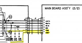
- Between the Digital Filter (YM3414) and the Serial-Parallel array, there appears to be 7 connections. I cannot identify 2 of these (labelled 'YDGL' and 'AOMT') - anyone know what they are?:

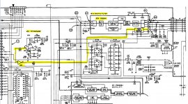
- I cannot seem to locate the player's muting circuit. I think it is somewhere in this section of the schematics:
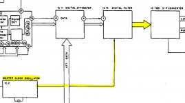
View attachment Q2_Muting Circuit.pdf - It appears from this simple block diagram that the player's world clock is passed through the Digital Filter to the Serial-Parallel array. However, I have my doubts when looking closer at the Schematics. Could it be that the Serial-Parallel array has it's own standalone connection with the master clock?


Hopefully you guys are able to help point me in the right direction!
Thanks,
Fish
Regarding YDGL, it appears to come from YM3414 Pin-1. In that case, from YM3414 data sheet it would appear to a deglitcher signal.
AOMT looks like it might monitor the reset status of PDE023. Unfortunately, can't find a datasheet for that chip.
Regarding the master clock, do you know or have you measured the clock frequency generated at IC2?
AOMT looks like it might monitor the reset status of PDE023. Unfortunately, can't find a datasheet for that chip.
Regarding the master clock, do you know or have you measured the clock frequency generated at IC2?
Full Service Manual here.....
( Pioneer PD-91 Compact Disc Player Manual | HiFi Engine )
YM3414 Datasheet....
( https://www.datasheetarchive.com/YM3414-datasheet.html )
From what I can gather from the YM3414 Datasheet, YDGL is the De-Glitch Signal and is indeed derived from a Clock in the Pioneer (Answers Q3 also I think).
AOMT I think is a Mute signal of some description. If you follow it back it is developed from the LOCS Pin 22 on the Main Micro. The line also joins with XRST (I presume a Reset line) and also goes off to the LCCS Switch. I think this is the 'Analogue/Digital/Both' Switch on the rear (?) / front (?) of the Player. I think therefore it's a Digital Mute line.
The Players overall Mute is done by Q's 511,512,611,612 fed from Q712. The MUTE line can be traced back to Pin 21 of the Main Micro (right next to Pin 21 as mentioned above lending credence to my theory that that too is a Mute of some sort).
P.
Regarding YDGL, it appears to come from YM3414 Pin-1. In that case, from YM3414 data sheet it would appear to a deglitcher signal.
AOMT looks like it might monitor the reset status of PDE023. Unfortunately, can't find a datasheet for that chip.
Regarding the master clock, do you know or have you measured the clock frequency generated at IC2?
Full Service Manual here.....
( Pioneer PD-91 Compact Disc Player Manual | HiFi Engine )
YM3414 Datasheet....
( https://www.datasheetarchive.com/YM3414-datasheet.html )
From what I can gather from the YM3414 Datasheet, YDGL is the De-Glitch Signal and is indeed derived from a Clock in the Pioneer (Answers Q3 also I think).
AOMT I think is a Mute signal of some description. If you follow it back it is developed from the LOCS Pin 22 on the Main Micro. The line also joins with XRST (I presume a Reset line) and also goes off to the LCCS Switch. I think this is the 'Analogue/Digital/Both' Switch on the rear (?) / front (?) of the Player. I think therefore it's a Digital Mute line.
The Players overall Mute is done by Q's 511,512,611,612 fed from Q712. The MUTE line can be traced back to Pin 21 of the Main Micro (right next to Pin 21 as mentioned above lending credence to my theory that that too is a Mute of some sort).
P.
Thanks Both!
 This has been very helpful.
 @Markw4: The player is currently with a friend, who is having a look at the transport. When it comes back I'll be doing some more tests.
@percival007 : Thanks to your keen eye, I can now see what you see about the AOMT in the Schematics. I feel like this is taking me in the right direction!
Where I'm at:
YDGL
It makes total sense that 'YDGL' is the de-glitch - that part is solved.
AOMT
What I need to understand better is exactly what the AOMT is doing and how the player is deals with 'muting', both digitally and on the output stage. Perhaps 'AOMT' stands for 'Audio Output Muting'?
The project I'm working on is to add a SPDIF interface (by tapping into the Digital Filter) to use the player as a red book DAC. I'm either going to replace the CD transport completely (which is dying) or keep both using some form of switch, likely the former as its less complicated.
I've got a DIR9001 SPDIF board that I think will work great.
I will obviously need to disable muting when using it as a DAC, as the player will think there is no CD playing.
Master Clock
I think the approach has to be that the master clock connection to the digital filter (which appears to supply the Serial-Parallel Array) needs to be disconnected. My theory is that the SPDIF interface is now going to act as the new master clock by recovering the clock from the stream.
"...the SPDIF interface is now going to act as the new master clock by recovering the clock from the stream."
That's one way to do it. A likely better way might be to use a local crystal master clock for the dac and a SPDIF receiver with an internal very high quality ASRC (one that can use the local master clock as the ASRC I2S output frequency reference). For example, maybe something like SRC4392.
Why SPDIF though? Asynchronous USB can perform better if properly implemented.