Dear community,
I've been recently working on my AMC CD9 player in which I first swapped the 3 stock NE5532 dual opamaps with Burson V6 vivid. Great improvement indeed.
Then I discovered through the Lampizator old website how to add a tube stage and completely get rid of opamps, thus, ideally getting an even better sound performance.
So I went ahead and built the tube stage into the CDP (schematics attached below).
The results are the following (referring also to the CDP output schematic attached):
I have to say that the mentioned differences are rather fine and took several listening tests. By know I hear them right away ;-)
Question to you: if I wanted to completely eliminate the opamps, is there anything I could try to change on the tube schematics or on the DAC output to improve the performance?
Thanks a lot
Fabrizio
I've been recently working on my AMC CD9 player in which I first swapped the 3 stock NE5532 dual opamaps with Burson V6 vivid. Great improvement indeed.
Then I discovered through the Lampizator old website how to add a tube stage and completely get rid of opamps, thus, ideally getting an even better sound performance.
So I went ahead and built the tube stage into the CDP (schematics attached below).
The results are the following (referring also to the CDP output schematic attached):
- When the signal is tapped right after the DAC (point A), the Burson opamps perform better than the tubes. The midrange is more focused and prominent
- When the signal is tapped from the output of the first half opamp (point B) then tubes + half opamp perform better than opamp only configuration. The midrange fills the space more, more focus and the overall sound is warmer.
I have to say that the mentioned differences are rather fine and took several listening tests. By know I hear them right away ;-)
Question to you: if I wanted to completely eliminate the opamps, is there anything I could try to change on the tube schematics or on the DAC output to improve the performance?
Thanks a lot
Fabrizio
Attachments
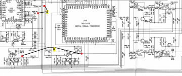
Note that the 1st opamps are driven at both their inputs, e.g. U203 by the DAC pins 11 and 14, and U202 by pins 18 and 21, resp. So they supposedly are differential amplifiers.
You might want to substitute them with tube diff amplifiers also. Not to be done with just two triodes per channel.
Best regards!
You might want to substitute them with tube diff amplifiers also. Not to be done with just two triodes per channel.
Best regards!
A Lampizator kit was my first tube project .
All tough happy with my first DIY working tube stage, I was a bit disappointed by the performance .
So changed the srpp design to 2 triode amplifiers, which can be done with just 1 tube, and never looked back .
Thanks Raaf, this was my first tube DIY too (no kit, however ;-)
Lampizator indicates also a stereo tube version (see pic). Is it what you mean?
Can you otherwise point me to any resource/schematic for the alternate circuit?
Attachments
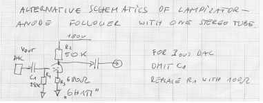
Yes , that is what I mean .
For sound improvement you could even skip C1 but it's electrically safer with .
Great, which tube did you use? I have 6H6P installed.
You probably need/there probably is some filtering done in the first opamp. These MASH dac´s outputs are extremely noisy. You´ll see that, if you measure the output on an oscilloscope. I´ve been playing around with Lampizators on a lot of different CD-players with excellent results over the years (using 6N16B-V though). The only circuits I never got good results out of were all those MN´s Mash converters ")
You probably need/there probably is some filtering done in the first opamp. These MASH dac´s outputs are extremely noisy. You´ll see that, if you measure the output on an oscilloscope. I´ve been playing around with Lampizators on a lot of different CD-players with excellent results over the years (using 6N16B-V though). The only circuits I never got good results out of were all those MN´s Mash converters
Hi Boydk, yes I saw the amount of noise coming out from the DAC at aorund 1.4MHz and I also believe that the first opamp role is mainly to filter. I must say I am very happy with my current setup. Now trying to improve and get completely rid of the opamps, if possible. Btw the Burson opamps are a very effective and easy improvement for anyone not wanting to go too too deep with modifications.
Voltage out Dac you can make opamp free with signal transformer , who acts also as filter.
You also try other opamps, that is cheaper then buy burson products.
With tubecircuits you can change sound by tuberolling different brands and types.
To do all the above you need to read a lot on this forum and try everything. We can not tell you what you like.
You also try other opamps, that is cheaper then buy burson products.
With tubecircuits you can change sound by tuberolling different brands and types.
To do all the above you need to read a lot on this forum and try everything. We can not tell you what you like.
Differential Tube Amplifier Options
Dear Kay,
I did some research and there's a plethora of potential topologies.
Considering that:
Thanks!
Note that the 1st opamps are driven at both their inputs, e.g. U203 by the DAC pins 11 and 14, and U202 by pins 18 and 21, resp. So they supposedly are differential amplifiers.
You might want to substitute them with tube diff amplifiers also. Not to be done with just two triodes per channel.
Best regards!
Dear Kay,
I did some research and there's a plethora of potential topologies.
Considering that:
- The DAC output is already strong enough to drive the power amp, I don't need much gain
- I can't use more than two tubes due to space constraints
- I'd like to possibly reuse the 6H2P tubes in place
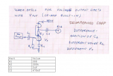
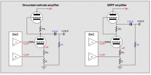
- Ground Cathode or SRPP (minimal change on the existing build) from tubecad.com
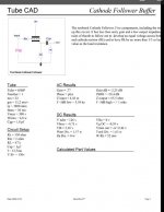
- Broskie's cathode follower (simplest solution), from tubecad.com
- White Cathode Follower, like for instance the one described here
Thanks!
Attachments
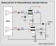

The original circuit has a seventh-order low-pass filter to get rid of all the ultrasonic quantization noise coming out of the DAC, the alternative circuit that you like has second-order low-pass filtering and the one that you don't like has no low-pass filter at all. Hence, I'd go for something that includes low-pass filtering as well as differential-to-single-ended conversion. You could take the second circuit from your last post and add an extra RC branch in front of it per DAC output to increase the filter order to two.
(If you should ever decide you also want to get rid of the DAC chip, see Valve DAC from Linear Audio volume 13 - but that takes a lot more than two tubes.)
(If you should ever decide you also want to get rid of the DAC chip, see Valve DAC from Linear Audio volume 13 - but that takes a lot more than two tubes.)
Last edited:
The original circuit has a seventh-order low-pass filter to get rid of all the ultrasonic quantization noise coming out of the DAC, the alternative circuit that you like has second-order low-pass filtering and the one that you don't like has no low-pass filter at all. Hence, I'd go for something that includes low-pass filtering as well as differential-to-single-ended conversion. You could take the second circuit from your last post and add an extra RC branch in front of it per DAC output to increase the filter order to two.
(If you should ever decide you also want to get rid of the DAC chip, see Valve DAC from Linear Audio volume 13 - but that takes a lot more than two tubes.)
Thanks Marcel,
If I understand correctly on Point A (in my initial post) there is already an RC filter (10k/220p) on all four signals (OUTR+/-, OUTL+/-). Are you suggesting to add another RC filter before either the SRPP or Broskie end stages?
If so which fc would you suggest? From the DAC I see a very strong 1.4Mhz spurious signal.
Thanks!
You're right, I took your remark about taking the signal from the DAC outputs too literally. At point A there is indeed already first-order filtering, so the version you don't like has first-order filtering and the version you do like second order.
So all in all, take the second circuit from post number 12 (filtered Broskie) and hook it up to points A. You then have a cascade of two first-order filters, the one between DAC and point A and the one in the filtered Broskie circuit. The fc has to be of the order of 80 kHz to match what you have now with one filter op-amp in the path.
Last edited:
You're right, I took your remark about taking the signal from the DAC outputs too literally. At point A there is indeed already first-order filtering, so the version you don't like has first-order filtering and the version you do like second order.
So all in all, take the second circuit from post number 12 (filtered Broskie) and hook it up to points A. You then have a cascade of two first-order filters, the one between DAC and point A and the one in the filtered Broskie circuit. The fc has to be of the order of 80 kHz to match what you have now with one filter op-amp in the path.
Excellent, I'll go with SRPP first (it's a very simple rework) and with Broskie afterwards. Will post both listening impressions as well as measurements ;-)

- Status
- This old topic is closed. If you want to reopen this topic, contact a moderator using the "Report Post" button.
- Home
- Amplifiers
- Tubes / Valves
- CD Player - Tubes vs. Burson OpAmps Output