")
Guys,
Would like to comment on the boost/cut levels proposed in various posts.
I've built up a few of the Palette Preamp Equalizer section from the original schematics. Used them a lot and came to some conclusions about the amounts of boost/cut actually needed.
Please remember that the Cello was designed to be a PROGRAM equalizer. Not a ROOM equalizer. As such, the amount of boost/cut NEEDED in the mid frequencies, combined with the ear's sensitivity at those frequencies, appears to be much less than at the frequency extremes.
Still using the same basic 6 frequencies as the original Palette, but now use boost / cut values of +-12dB at 20hx and 20K; +- 8dB at 120hz and 5K; and (only)+-4 dB at 400/800 hz (switchable) and +- 4db @1K/2Khz (again switchable.
Did put the Equalizer section in a nice small box (see Pictures of 2 versions) on the end of a 10M umbilical that plugs into my DIY Cello Encore Line Stage. Can dial-in the EQ; adjust the gain of each channel by 3dB or so and defeat the equalization FROM the LISTENING POSITION.
Use it a lot to "tame" bright CD's and "boost" deficient bass on older LP's. Amazingly, in many cases only ONE to TWO dB is all that is needed in the midrange.
stellavox,
Are you willing to share the circuit inside your EQ? I for one would really like to see it.
The circuit is basically the same as shown in Chapter 2.17 of the 1977 National Semiconductor Audio Handbook. For some reason, rather than putting all the bands in parallel, Coelangelo decided to put some of the bands in series and some in parallel. I can look up the schematics but all the individual center frequency/band width schematics are the same but with different R/C values. Used OPA 627's with OPA 633 followers. Total of 18 627's - maybe a few more in the line stage that followed! The fancy unit in the picture has the stock EQ board inside - think I have a picture. Another Line Stage board was mounted on the top (or maybe bottom). The NOS boards I got all had noisy Sfernice pots - had to change them out. Smaller unit had the board re-laid out.
The Palette Preamplifier was supposed to be a less-expensive clone of the original Palette. Maybe 80% (my estimate) of the performance at <50% of the cost. Have production quantities of their products somewhere.
Just looked up the sales info - Cello sold around 700 Audio Palette's and 500 Palette Preamps
Last edited:
The circuit is basically the same as shown in Chapter 2.17 of the 1977 National Semiconductor Audio Handbook. For some reason, rather than putting all the bands in parallel, Coelangelo decided to put some of the bands in series and some in parallel. I can look up the schematics but all the individual center frequency/band width schematics are the same but with different R/C values. Used OPA 627's with OPA 633 followers. Total of 18 627's - maybe a few more in the line stage that followed! The fancy unit in the picture has the stock EQ board inside - think I have a picture. Another Line Stage board was mounted on the top (or maybe bottom). The NOS boards I got all had noisy Sfernice pots - had to change them out. Smaller unit had the board re-laid out.
The Palette Preamplifier was supposed to be a less-expensive clone of the original Palette. Maybe 80% (my estimate) of the performance at <50% of the cost. Have production quantities of their products somewhere.
Just looked up the sales info - Cello sold around 700 Audio Palette's and 500 Palette Preamps
Thanks for the heads up about that National Handbook. Having modelled it with the 6 Palette bands and compared it to the Burwen/Cello characteristics, it is identical. It has precisely the same frequency response with regard to pot setting. Now of course, the Audio Palette used switched resistors, and a 60 position custom switches to get precise dB boost and cut setting. Now it is possible to do that with Seiden switches with 6 degree indexing, or a similar Shallco unit - but the price for 6 stereo switches is completely prohibitive (well over a grand). I know - I went so far as to get quotes!
So the only sensible option is to use linear stereo pots, such as were used in the Palette Preamplifier. That gives a non-linear setting of boost/cut to pot rotation, worst for the 15Hz and 25kHz filters. If you look closely at the Palette Pre, you can see that the settings reflect that behavior.
The good thing is that the National circuit uses one op-amp per cell, whereas the best I managed with the Burwen/Palette was three per cell.
The only problem with the design rules in the National is that for a given characteristic (frequency, and maximum boost) it calculates resistor values, at fixed resistor and capacitor ratios, and the capacitor values come out as awkward values. Since capacitors are only available in a relatively few values, but resistors are cheap and in E96 series easily, a preferred design rule would be to chose common capacitor values, and then work out the resistors to meet the design goals. Rather then fight the equations, I have hand optimized the resistor values using commonly available 1% tolerance polypropylene or polystyrene capacitors to be identical to the Audio Palette responses. And decreased the pot value and summing resistor values to get noise down.
So when I get around to building mine, I will definitely be using the 1977 National Semiconductor Audio Handbook circuit. So thanks Stellavox!
THANKS BACK Sawyers,
Main comment - as expressed in a previous posting.
From doing a LOT of listening to the original Pallete Pre (IC version) found that most of the bands had too much boost/cut. Never ended up turning the original knobs too much.
SO in my latest unit, I reduced the low Khz to +/- 4db; 120hz/5Khz to +/-8dB and the frequency extremes to +/-12db.
ALSO - to make it really usable, I put the EQ portion in a separate box. With an 20ft umbilical so I could adjust it from the listening position. Added an IN/OUT switch (really necessary- activates relay back in the line stage) and ~6db gain trim pots for each channel. Pic attached
Attachments
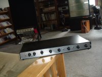
Nicely built unit!SO in my latest unit, I reduced the low Khz to +/- 4db; 120hz/5Khz to +/-8dB and the frequency extremes to +/-12db.
ALSO - to make it really usable, I put the EQ portion in a separate box. With an 20ft umbilical so I could adjust it from the listening position. Added an IN/OUT switch (really necessary- activates relay back in the line stage) and ~6db gain trim pots for each channel. Pic attached
Reminds me of the box I built a while ago which is a combination tape recording/switching and Hughs S.R.S. enhancement system.
Thanks wiseoldtech!
Sawyers, this latest exchange got me thinking about a "situation" I ran into when comparing the "Burwen vs National" configuration of the individual EQ bands. In the National configuration, all the individual band boost/decrease circuitry "modules" are in PARALLEL. The Burwen/Cello configuration has the "modules" in a series-parallel arrangement. More specifically, in the IC Palette Pre, the 20hz; 50hz; 2Khz and 20Khz sections are in PARALLEL but then in SERIES with a 120hz and (again series) 5Khz section. I haven't checked my notes to see if the discrete, ORIGINAL Palette is configured in the same way, According to the National information (and others who have used this configuration), a parallel configuration yields lower noise along with much less NET op-amp output offset than any series configuration. Meant to contact Burwen and ask (if he remembers) why he did this. I did run into the offset problem but don't remember (myself) what I did about it.
Regarding the use of 2-deck linear pots - Believe the ones I used were Alpha - from Mouser. Did find some nice, green British ones on the Bay at the time. Noth worked fine and I never noticed any inter-channel, gain tracking problems in use.
Interestingly, one problem I and a few friends who I built units for experienced, is that once you start using a program equalizer you can, like, never stop "twiddling" with it (for a particular recording). And then once you think you're there, you hit the bypass switch and S**T. Had to discipline myself to spending no more than, say, a minute "adjusting" things, then LEAVE IT ALONE. Of course this results in an "ear training", learning process of how much a certain amount of boost/cut at a certain center frequency affects the SOUND. It was a good experience and I could/can then also relate the sound effects at certain frequencies, which made/makes the NEXT trial that much quicker and easier.
Charles
did I get effect/affect right???
Last edited:
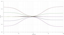
Charles - I spent some time modelling the original Burwen as a starting point. Yes he has the 15Hz, 500Hz, 2kHz and 25kHz responses in parallel (into a summer). And then a rather strange circuit for the 120Hz and 5kHz. But these two controls actually give a Baxandall-type response (attached).
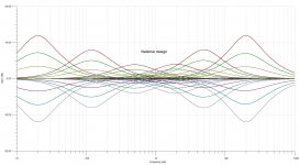
The discrete Audio Palette did away with that, from what I can see, and understand from the block diagram you posted, Colangelo put everything in parallel using multiple feedback filters (in the same way as Burwen's 15Hz, 500Hz, 2kHz and 25kHz filters.)
I think there is a lot to gain by putting everything in parallel. Both simplicity and potentially lower noise. I suspect that in the Palette Pre four were in parallel, and the other two in series because the input resistance of an all parallel National implementation is rather low (~80 ohms without anything boosted), so would need ideally a buffer in front of each filter. Or a buffer with chunky output drivers (Walt Jung published something on that approach).
My version might be harder to drive than a pure National, because I reduced the pots from 100k to 10k to keep the noise down. Of course other resistors tend to scale with that and take a higher drive current. Anyway I'm still playing with values to get an optimum of noise and drive ease.
Craig
Attachments
Last edited:
Incidentally, the Burwen/Audio Palette used multiple feedback filters. An excellent design tool for these is here http://sim.okawa-denshi.jp/en/OPtazyuBakeisan.htm
So if anyone wants to go the original design route, that is a good place to start.
So if anyone wants to go the original design route, that is a good place to start.
OK - I've been going through the filter table on FC-1 schematic. I put the full schematic of OTA-1 into Microcap, And then put the external components and the filter around it.
The numbers I get are:
15Hz, bang on.
120Hz, actually 83.5Hz
500Hz bang on
2kHz actually 2.44kHz
5kHz actually 13kHz!
25kHz, close enough at 26kHz
The one that is really far out is 5kHz.
Now the center frequency of the multiple feedback filter employed is given by f0 = 1/(2pi x root(1/(R1R2C1C2)). That can be rearranged to give R1R2 = 1/(CiC2 x (2pif0)^2)
Now for the 5kHz filter C1 = 22nF and C1 = 2.2nF. Which give R1R2 = 2.1 x 10^7. But the filter table resistor values of 1.1k and 2.74k gives 3 x 10^6. This is a factor of 7 low, So the frequency goes up by root 7 = 2.65, and 2.65 x 5000 = 13.2kHz - which is what the simulation confirms.
The correct values for a final boost of 12dB at 5kHz (once the final feedback loop is closed, which requires a Q of 1) is R1 = 1.3k ohms and R2 = 15.8k (the product of which is 2.1 x 10^7). That is confirmed through simulation.
The particularly interesting thing is that three bands are bang on or close. And three seem to have significant errors, which is very strange. Although there is published data on the Palette Pre (in Stereophile) there seems to be no published information on the discrete Audio Palette.
Anyone have any ideas about this? Charles?
Craig
In an earlier mail I plotted out the Baxandall-type characteristics of the 120Hz and 5kHz filters of Burwen's early work on the Audio Palette. I thought this was very odd, and spent quite some time trying to find out what was going on. Then I looked at the spec at the beginning. Burwen says of these filter frequencies:
120Hz control +/-14.5dB @ 15Hz in 0.5dB steps
5,000Hz control +/- 12dB @ 25kHz in 0.5dB steps
Which confirms the Baxandall curves.
This means that in Burwen's design, with the 15Hz control at maximum (29dB) and the 120Hz control at maximum of 14.5dB, the combined boost at 15Hz will be 43.5dB! And likewise at 25kHz, 36dB!!
Anyway the topology of Burwen's early Cello design is that the 15Hz, 500Hz, 2kHz and 25kHz are in parallel, (and have similar shapes to the Palette Pre). Then the Baxandall sections are in series with those.
Craig,
Regarding the "mistakes" you found in your simulations. Just checked the drawings/prints I have of the Palette and realize from their 1985 dates that they are probably the FIRST set of drawings produced for the unit. - even have some prints of hand-drawn schematics. And realized that the prints don't (yet) have drawing or revision numbers. There could well have been later drawings with "corrections". Have found numerous mistakes on these and other drawings.
Don't want to be too hard on the Cello folks tho. Their documentation was designed for MANUFACTURING; so what was important was the PC board LAYOUTS; the parts list of course; chassis layout showing where to put the individual modules/controls/connectors went AND interconnection lists so the correct sized wires could be chosen / cut /prepaired (ends stripped), and where each one went to/from. Circuit diagrams were only ever made of the individual amplifying/control/protection modules and probably didn't have to be referred to often/ever, so error checking was way down on their list. Unfortunately at the time I overlooked any version numbers on drawings and didn't care about parts lists.
FWIW - documentation or lack thereof is common between a few audio companies that I have had access to - namely Levinson / Cello and Krell. No comprehensive service manuals; hand written, sketchy set-up procedures but good final test documentation/reports for each unit. All info was geared toward "getting the product out". And to their credit very few, if any, ever came back. Good for them. But not good for us 30/40 years later.
Charles
- Home
- Source & Line
- Analog Line Level
- Cello Palette Style EQ Design (was High End Tone Control)...