My class D amp outputs a "bridge" differential signal for each speaker. You could achieve the same thing connecting from the "in-phase" left output to the "out-phase"right output.
Unsure what that would do to the fault protection circuitry in the class D amp, so I probably wont try it. (Where would I put a 15" center channel speaker anyway? Has to be the same speaker type, to have the same voicing done via the system DSP)
I used to connect speakers L+ to R+ on a stereo output all the time, to make a "center-ambient" channel. Good use for those speakers you only happen to have 1 of. One listener told me it seemed to improve the bass - go figure - in phase with one channel, out of phase with the other.
Neat trick how they did it by grounding the 4 ohm tap to create the "bridged" mono out. Anything to add a feature setting your product apart from the ordinary...
I wonder if you could make a single speaker guitar amp out of an "integrated" tube stereo amplifier in this way? Just like Doublemint gum; two mints in one!
RE: Post # 7 schematic:
The impedance of the various output taps:
With both the L and R 4 Ohm taps grounded, that means that the C taps are (- phase) 4 Ohms away from ground.
And that means that the 16 Ohm taps are ( + phase) 4 Ohms away from ground.
We have one end of a "center" speaker connected to the L channel - phase 'common' tap which is 4 Ohms away from ground; and the other end ofthe "center" speaker connected to the R channel + phase tap that is 4 Ohms away from ground.
Now we are loading the various Ohm taps with a L and R speaker, and at the same time with a center speaker.
That means they outputs are nominally overloaded.
Probably should connect L and R speakers this way:
16 Ohm L and R speakers to 8 Ohm taps.
8 Ohm L and R speakers to 4 Ohm taps.
And 4 Ohm L and R speakers to 4 Ohm taps (Oh, but the center speaker is already loading the taps).
And the center channel speaker should be either 8 or 16 Ohm.
As I said in my earlier post, if you want optimal center channel performance, use another amplifier for the 3rd channel.
Thank´s for answer.
I don't need a center channel.
I have asked out of curiosity and knowledge.
Previously I did tests on one of the amplifiers that I built, to see how a central channel works.
The results of those tests I published in post # 15, please read them.
The circuit, and the amplifier in attachments.
Thank you very much for all the answers.
Best Regards
Gusmore
Attachments


Your schematic in post # 23 of this thread is completely different than schematics in your earlier posts in this thread.
What schematic did you use when you did tests of an amplifier in Post # 15?
Were you using the amplifier in the schematic of post # 23?
Thanks for enlightening us.
What schematic did you use when you did tests of an amplifier in Post # 15?
Were you using the amplifier in the schematic of post # 23?
Thanks for enlightening us.
Last edited:
Your schematic in post # 23 of this thread is completely different than schematics in your earlier posts in this thread.
What schematic did you use when you did tests of an amplifier in Post # 15?
Were you using the amplifier in the schematic of post # 23?
Thanks for enlightening us.
Thank´s for answer !
The Tests in post # 15 are done on my amp, which I built, and in post # 23 I show this.
I definitely did the tests on my amp.
My stereo amplifier have the output transformers where their respective secondaries have 3 taps, 4 ohms, 8 ohms, and common (common to ground).
1) if one connects R tap 8 ohms, and L tap 8 ohms the sound is rare, and cut off, the voices are not heard or are heard poorly.
2) if one connects R tap 4 ohms and L tap 8 ohms, the sound is much better, the voices are heard, predominantly treble, mid-range, and bass attenuation.
3) If one connects R tap 8 ohms and L tap 4 ohms the sound is much better too, but different, and inverse to 2).
Look at my amp, and circuit, in attachments
Best regards
Attachments


Gusmore,
1. Connecting a speaker across L and R taps of equal Z, like L4 and R4, or L8 and R8
will get you the Difference of the L and R signals.
This is the spread of the stereo signal.
It does Not give you a center channel.
This is L - R.
2. Connecting a speaker across the L and R taps of unequal Z, like L4 and R8; or L8 and R4
will give you some of the 4 Ohm channel, and more of the 8 Ohm channel.
Again, you are getting the difference of the L and R channels, just more of the 8 Ohm tap channel. And this is the spread of the stereo signal.
This is either L - 1/2R; or 1/2L - R.
This does Not give you a center channel.
Locating a 3rd speaker between the L and R speakers and using method # 1 or # 2 above does Not make a center channel.
Do you want to try using a real center channel?
. . . even without a third amplifier channel?
You need two 8 Ohm 25 Watt power resistors.
Connect one 8 Ohm resistor from L 8 tap to the center speaker + terminal.
Connect one 8 Ohm resistor from R 8 tap to the center speaker + terminal.
Connect the center speaker - terminal, to the Common output tap of the amp.
Now, you will have a true Center Channel speaker.
The sound coming from that center channel speaker is L + R.
Problem Solved!
Last edited:

All kinds of fun is a lot like playing with a Moog Synthesizer.
It sounds great!
But a Moog Synthesizer can not sound like original music productions in J S Bach's time.
L-R/2 and R-L/2 do not sound very much like what was recorded in the studio.
Well, sort of, just a different mix.
And just remember, this thread started in Post # 1 with a Fisher X101D, that had a "Center Channel" Out.
But it was actually found that the Fisher X101D a L - R output (or R - L output), which is not in the center;
the Fisher X101D is not a L + R which would be a true center channel out.
Putting any arbitrary signal on a speaker, and than locating it in the center between the L and R speakers, does not always make it a true center speaker.
I hope that clarifies the mis-nomer that Fisher used.
Last edited:
I think Bach on a Moog would work quite well - if I have a moment (it will have to be a digital Moog sorry).
Nobody would make an amp with a L-R output. I've looked at the Fisher X101D schematic again in #7 and the centre speaker is taken from the black of the top transformer and yellow of the bottom so we get +L on one terminal and -R (not +R) on the other. This will produce L+R. The headphones are also wired correctly.
Using
L-R/2 = L/2 + (L-R)/2
R-L/2 = R/2 - (L-R)/2
is just a way of widening the stereo image, it can project the image beyond the speaker position. If you add in a centre you will narrow the image
Using
L-R/2 = L/2 + (L-R)/2
R-L/2 = R/2 - (L-R)/2
is just a way of widening the stereo image, it can project the image beyond the speaker position. If you add in a centre you will narrow the image
Last edited:
baudouin0,
A mono recording, or a singer in the center of a stereo recording is played.
The sound appears to come from the center, and everything is great!
OK.
Now, for the problem many are not aware of, with using a center speaker:
Suppose a recording is played that has a Trumpet in the Left channel, and a Clarinet in the Right channel.
First, only the Trumped plays, you get full amplitude out of the Left speaker, and - 6 dB out of the center speaker (that "pulls" the Trumpet image toward the center, but not all the way to the center).
Second, only the Clarinet plays, you get full amplitude out of the Right speaker, and - 6 dB out of the center speaker (that "pulls" the Clarinet image toward the center, but not all the way to the center).
Third, now both the Trumpet plays, and the Clarinet plays at the same time.
You get the Trumpet and the Clarinet playing fairly close together, and not as far apart as they were in the recording.
Well, that is the performance tradeoff of the best center speaker setup that you can get.
A center speaker may have been a real good idea for the "ping pong" effect stereo recordings of many decades ago.
Nicht so Gut on todays recordings.
Last edited:
Yes in the early days the recordings were a bit bizarre with things panned all the way over to left and right. I sure it was just a cost and space saving exercise to just have a single big speaker. Stereo imaginary is a subject in itself and has just as much to do with phase as amplitude. Modern music is in fact mostly mono and the stereo (L-R) part is used mainly to add ambiance and presence. The modern equivalent of the centre speaker (for music rather than films) is the sub woofer but the difference here is that low frequencies don't convey direction for the ears as the wavelength is too large. There's no reason you could not use this amp with single a sub woofer and some bookshelf speakers.
Last edited:
Gusmore,
1. Connecting a speaker across L and R taps of equal Z, like L4 and R4, or L8 and R8
will get you the Difference of the L and R signals.
This is the spread of the stereo signal.
It does Not give you a center channel.
This is L - R.
2. Connecting a speaker across the L and R taps of unequal Z, like L4 and R8; or L8 and R4
will give you some of the 4 Ohm channel, and more of the 8 Ohm channel.
Again, you are getting the difference of the L and R channels, just more of the 8 Ohm tap channel. And this is the spread of the stereo signal.
This is either L - 1/2R; or 1/2L - R.
This does Not give you a center channel.
Locating a 3rd speaker between the L and R speakers and using method # 1 or # 2 above does Not make a center channel.
Do you want to try using a real center channel?
. . . even without a third amplifier channel?
You need two 8 Ohm 25 Watt power resistors.
Connect one 8 Ohm resistor from L 8 tap to the center speaker + terminal.
Connect one 8 Ohm resistor from R 8 tap to the center speaker + terminal.
Connect the center speaker - terminal, to the Common output tap of the amp.
Now, you will have a true Center Channel speaker.
The sound coming from that center channel speaker is L + R.
Problem Solved!
6A3sUMMER, Thanks again for answer!
I will do the test according to your method.
Just out of curiosity and knowledge
Look at your center channel diagram on the circuit, and let me know if I understood correctly!
A question: what impedance should the center speaker have?
Best regards
Gusmore
Attachments

Gusmore,
Re-read my post # 31 to see what the sonic effects of a center speaker are.
You will be double loading the amplifier output taps (lower than what they were designed for).
Suppose you use 8 Ohm L and R speakers on the 8 Ohm taps.
And Suppose you use an 8 Ohm center speaker, with the 8 Ohm power resistors just as you have drawn on the schematic of post # 33.
The center speaker and two 8 Ohm resistors will provide an 8 Ohm load on those 8 Ohm taps.
That means you are double loading the 8 Ohm taps with effectively 4 Ohms.
So put all those loads (L, R, and Center) on the 4 Ohm taps, instead of the 8 Ohm taps.
The impedance of loudspeakers is not constant versus frequency (actually dips below the manufacturers nominal rated impedance, but we do this all the time with just L and R speakers, so using the 4 Ohm taps with L, R, and Center makes it OK).
And the effect of pulling the stereo spread more to the center will depend on the relative efficiency of the L and R speakers, versus the efficiency of the center speaker.
Have fun. Try vintage recordings and modern recordings. Different sonic effects.
Interesting circuit for a PA.
Please clarify what you mean, and also explain it.
Best regards
Gusmore
Oh the pentode drivers (which is what I did in an amp) and the feedback from the OPT primaries and the combined pentode/triode in the first stage. Just a combination I have not seen.
baudouino, thank´s for answer.Oh the pentode drivers (which is what I did in an amp) and the feedback from the OPT primaries and the combined pentode/triode in the first stage. Just a combination I have not seen.
My language is Spanish, please excuse how I write in English.
I comment on the technical characteristics of the amplifier that I have built:
The power amplifier (1 channel) is made up of 4 stages and at maximum excursion it delivers more than 50 W rms with a THD less than 0.1%, and less than 1% by intermodulation, the frequency response is flat between + - 0 , 5 dB from 10 hz to 50Khz, the input sensitivity is 0.4v rms for 50 W output, and the total noise and hum is 70db below 50 W, it operates in class AB1 push-pull, fixed bias.
The 1st stage is the input voltage amplifier and is operated by the pentode section of valve 7199, the output of this stage (pentode plate) connects directly to the grid of the triode section of the same valve.-
The 2nd stage is the phase inverter and is operated by the triode section of this same valve, and as previously indicated by the amplified signal coming from the plate of the pentode section, it connects directly to the grid of the inverter triode section, the inverter phase is split-load type ( cathodyne / concertina), simple, but very efficient and precise, the plate and cathode voltage outputs are equal in amplitude and phase opposition; The use of direct coupling between these two stages is to minimize the phase inversion shift and consequently to be able to increase the NFB values to be used without any danger of oscillation or low frequency instability.
The 7199 is a very low noise and hum Hi-Fi valve, miniature type, pentode / triode, 9 pin miniature socket (noval), heater 6.3 V, 0.45 A, developed by RCA, and designed pure and exclusively for Hi-Fi audio applications, today they are no longer manufactured, but new NOS are still available, it is important to mention that there is no satisfactory replacement for this valve, however some replace it (after rewiring the base of the chassis , because they have different connections) by 6U8, 6GH8; or 6AN8, which have somewhat similar characteristics, but not at all the same, that makes the performance very poor and inferior compared to 7199.-
The 3rd stage is the last voltage amplifier, they are the drivers, whose function is to excite the power valves, this stage is operated by 2 6CB6A valves, sharp cut-off pentodes, and they work in push-pull.
The 6CB6A is a miniature type sharp cut-off pentode, heater 6.3 V, 0.3 A , and 7 pin miniature socket, it was widely used in radio frequency and as a class A voltage amplifier, today it is no longer manufactured more, but new NOS are achieved.-
The 4th stage is the power stage, it is operated by 2 Hi-Fi 7027A valves, beam power pentodes, and they operate in push-pull, class AB1, fixed bias.
The 7027A is a Hi-FI valve, beam power pentode, heater 6.3 V, 0.9 A, 8-pin socket (octal), 35W plate dissipation, developed by RCA and designed exclusively for high quality and high fidelity audio output.-
Today it is manufactured in Slovakia by JJ electronic (ex Tesla), and in Russia by New Sensor (Ex Reflektor) with the brands Sovtek, and Tung-Sol, these valves they have less power than NOS, since they dissipate 30 W of plate.-
But there are also new NOS, 35W of plate dissipation, brand RCA, Sylvania, General Electric.-
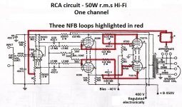
The excellent performance of this amplifier must be attributed, in part, to the use of a 450 V plate supply and 400 V electronically regulated for the screen grids (g2) of the 7027A beam power pentode, as well as the use of 3 negative feedback loops (NFB), the traditional loop from the secondary winding of the output transformer to the cathode (pentode section of 7199) of the 1st input amplifier, then the loop that goes from the plates to the grids (g1) of the valves 7027A, and lastly, the loop that goes from the 7027A plates to the cathodes of the 6CB6A drivers, see in the circuit diagram, the 3 NFB loops outlined in red .-
Other characteristics that contribute to the excellent performance of the amplifier are:
The heaters of all valves operate with positive potential (+ 65V) with respect to ground, in order to minimize hum , and in the power supply it has the adjustment control referred to for minimum hum.-
Adjust control fixed bias of the 7027A, in the power supply.
Adjust control Regulated voltage for screens (g2) of the 7027A, in the power supply.
Adjust control for ac balance of the 6CB6A drivers, in the amplifier.-
See the attachments :
Best regards
Attachments


Last edited:
Many thanks for the info I used and couple of EF184's as drivers for an amp so was interested in your approach. The use of multiple NFB is clever and minimises the main NFB which can be problematic with lag in the OPT. 50W .1% THD is very good going. It nice to see something a bit different which does offer better performance.
Last edited:
- Home
- Amplifiers
- Tubes / Valves
- Center Channel Stereo Tube Amp