Hello all,
Have decided to take one of my sucessfull prototypes and create a low powered simpler version.
The basics of my design methodology is to have minimum loading on the VAS at audio frequencies and keep healthy stability margins.
Features of design:
1) CFA front end
2) Edmond Stuart based CMCL VAS
3) Two pole bootstrapped shunt compensation at VAS output
4) A combination of symetrical TMC and TPC
5) Hawksford Error Corrected OPS with cascoded drivers
6) DC Servo
7) Two pole input filter
The goal is to keep the key features while removing any excess complexity that does not add any benefit.
Basic simulation results:
GNFB PM = 82 degrees / GM = 32dB
1 kHz 4.4V pk - pk into 8R = 0.000002%
1 kHz 44V pk - pk into 8R = 0.000018%
20Khz 4.4V pk - pk into 8R = 0.000038%
20Khz 44V pk - pk into 8R = 0.000649%
20Khz 44V pk - pk into 4R = 0.001046%
Don't think any more progress needs to be made with respect to THD. Layout issues and parasitics will probably be more of an issue.
Any comments are much appreciated. Would like to develop this amp first and build a prototype. I think it will work since a more complex version of this has been built and blown up")
Thank you for reading this.
Paul
Have decided to take one of my sucessfull prototypes and create a low powered simpler version.
The basics of my design methodology is to have minimum loading on the VAS at audio frequencies and keep healthy stability margins.
Features of design:
1) CFA front end
2) Edmond Stuart based CMCL VAS
3) Two pole bootstrapped shunt compensation at VAS output
4) A combination of symetrical TMC and TPC
5) Hawksford Error Corrected OPS with cascoded drivers
6) DC Servo
7) Two pole input filter
The goal is to keep the key features while removing any excess complexity that does not add any benefit.
Basic simulation results:
GNFB PM = 82 degrees / GM = 32dB
1 kHz 4.4V pk - pk into 8R = 0.000002%
1 kHz 44V pk - pk into 8R = 0.000018%
20Khz 4.4V pk - pk into 8R = 0.000038%
20Khz 44V pk - pk into 8R = 0.000649%
20Khz 44V pk - pk into 4R = 0.001046%
Don't think any more progress needs to be made with respect to THD. Layout issues and parasitics will probably be more of an issue.
Any comments are much appreciated. Would like to develop this amp first and build a prototype. I think it will work since a more complex version of this has been built and blown up
Thank you for reading this.
Paul
Attachments
Last edited:
Member
Joined 2009
Paid Member
Thank you.This is way beyond my skill level but it sounds like a most interesting project
It's way beyond my skill level too but persistance always wins.
The second but last prototype was this amp with feedback baker clamps and 4 pairs of MOSFETs all with their own drivers + cascodes. All on stripboard. You don't want to know how long it took to tame the MOSFETs.
How to adjust the output error correction?
The first implementation will a stripboard prototype. The thinking is, if it works on stripboard with compromised layout, it should work with a proper PCB.
The error correction is currently set with current through R11 and R12 the same as R16 and R17. It is stable this way.
Version 2 and some plots
Update on development so far.
Have gone back to the tian probe method of getting loop gain. Significant diferences between the tian probe and the version in Bob Cordells book.
The changes:
1) Added Goatee's DC servo. Needed a higher order filter. Loop gain was being destroyed at loop frequencies.
2) Added resistor to compensation network to smooth the loop gain plots.
3) Increased MOSFET gate stoppers a little.
4) A few minor tweaks to compensation component values.
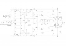
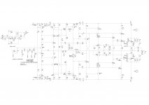
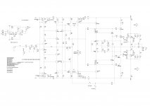
Here is the new schematic and some plots.
1) Schematic
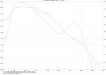
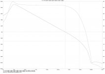
2) Group delay ( I'm especially pleased with this)
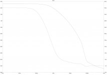
3) Loop Gain of OPS loop
4) GNFB Loop Gain
Comments welcome as always.
Thank you for reading this.
Paul
Update on development so far.
Have gone back to the tian probe method of getting loop gain. Significant diferences between the tian probe and the version in Bob Cordells book.
The changes:
1) Added Goatee's DC servo. Needed a higher order filter. Loop gain was being destroyed at loop frequencies.
2) Added resistor to compensation network to smooth the loop gain plots.
3) Increased MOSFET gate stoppers a little.
4) A few minor tweaks to compensation component values.
Here is the new schematic and some plots.
1) Schematic
2) Group delay ( I'm especially pleased with this
)3) Loop Gain of OPS loop
4) GNFB Loop Gain
Comments welcome as always.
Thank you for reading this.
Paul
Attachments
Last edited:
Update on development so far.
Have gone back to the tian probe method of getting loop gain. Significant diferences between the tian probe and the version in Bob Cordells book.
The changes:
1) Added Goatee's DC servo. Needed a higher order filter. Loop gain was being destroyed at loop frequencies.
2) Added resistor to compensation network to smooth the loop gain plots.
3) Increased MOSFET gate stoppers a little.
4) A few minor tweaks to compensation component values.
Here is the new schematic and some plots.
1) Schematic
2) Group delay ( I'm especially pleased with this
3) Loop Gain of OPS loop
4) GNFB Loop Gain
Comments welcome as always.
Thank you for reading this.
Paul
Paul, Could you post .asc file, I would like to simulate it.
On a quick look I notice that your input LP filter is the source output impedance sensitive, it uses quite high capacitances.
Damir
... back to the tian probe method...
Better choice, especially for the internal loops. You have checked the internal loops?
Very important once you use advanced feedback techniques.
The PM you quote for the outer loop is basically irrelevant.
If I understand your probe use correctly then an important loop has only 60 PM, tolerable but lower than I like.
Best wishes
David
Last edited:
If I understand your probe use correctly then an important loop has only 60 PM, tolerable but lower than I like.
Best wishes
David
What minimum PM do you like to achieve? and minimum gain margin?
Member
Joined 2009
Paid Member
You don't want to know how long it took to tame the MOSFETs.
I still remember my first experience with MOSFETs, I think I spent many days with a soldering iron to no avail and ended up re-spinning the pcb design twice to get it working !
Damir,
Thank you for veiwing my amp. Here is the .asc file. Would be good for you to simulate. I'm sure it can be optimised for more performance but my priority at the moment is to get good stability. All models are either LTSpice or Cordell. You are right about the input filter. What values do you recommend?
David,
Internal loops is where I still struggle. Have checked the two loops associated with the "TMC" style compensation and the CMCL.
The loop with PM = 60 is the "TMC" loop around the OPS. I ike to aim for around 75 to 85 degrees PM for loops. 75 degrees is good according to other control theory from what I have read.
Beginner question again. Why is the PM of the outer loop irrelevant?
Can I ask for you assistance with the loop analysis? I know I have many loops in this and would like all loops to stable.
Many thanks,
Paul
Attachments
I still remember my first experience with MOSFETs, I think I spent many days with a soldering iron to no avail and ended up re-spinning the pcb design twice to get it working !
I feel your pain
It's a good learning experience though. Finding out how to deal with the parasistics.
The harder the journey the more satisfying it is in the end.
Why is the PM of the outer loop irrelevant?
The PM of the outer loop IS relevant, but what you have probed is not actually the outer loop, if I understand your probe point correctly.
Can I ask for you assistance with the loop analysis? I know I have many loops in this and would like all loops to stable.
Sure, bed time here now but more tomorrow, also for Bimo
Best wishes
David
Paul, I suggest some changes, but don't take it as a suggestion from an expert as I am not.
1. Don't use lifted ground in the simulation. It is used in real circuit to separate signal ground from main ground, but both should be connected to the star ground so both grounds are on the same zero potential.
2. Connect TMC resistor after the Tian probe, in this case you will see two pole behavior and include TMC in bode plot, but David will explain much better and how to simulate local loop.
3. Why do you use R66 to the ground? I suppose you want to simulate both, TMC and TPC and compare. Problem is that TMC capacitors optimization is not the same as for TPC. I changed TMC capacitors. Why do you use C4, I think it is not needed, as there is no peaking even without it.
4. With your input LP filter, -3 dB is 235 kHz for zero source output impedance, but it drops to 38 kHz for 1kohm source output impedance, and in some cases the source output impedance could be even higher.
I suggest lower capacitors and higher resistors for input LP filter and with that you got 366 kHz and 195 kHz respectively.
Damir
Attachments
The PM of the outer loop IS relevant, but what you have probed is not actually the outer loop, if I understand your probe point correctly.
I think we should start from the beginning with analysing the loops
Have lost confidence in my loop analysis now... No reason to not learn though. What I do know is that the basic topology works in real life. The only significant difference is that a diamond buffer was used in the real life circuit.
The feedback resistor was dropped down to 1K and the amp was still stable (useable). I think 470R was about as low as it would take. Whether everything was stable is questionable but you could put reactive loads on the output and it would still produce good square waves. And it did play music.
Sure, bed time here now but more tomorrow, also for Bimo
Best wishes
David
Thank you. Any help would be much appreciated.
Paul
Paul, I suggest some changes, but don't take it as a suggestion from an expert as I am not.
1. Don't use lifted ground in the simulation. It is used in real circuit to separate signal ground from main ground, but both should be connected to the star ground so both grounds are on the same zero potential.
2. Connect TMC resistor after the Tian probe, in this case you will see two pole behavior and include TMC in bode plot, but David will explain much better and how to simulate local loop.
3. Why do you use R66 to the ground? I suppose you want to simulate both, TMC and TPC and compare. Problem is that TMC capacitors optimization is not the same as for TPC. I changed TMC capacitors. Why do you use C4, I think it is not needed, as there is no peaking even without it.
4. With your input LP filter, -3 dB is 235 kHz for zero source output impedance, but it drops to 38 kHz for 1kohm source output impedance, and in some cases the source output impedance could be even higher.
I suggest lower capacitors and higher resistors for input LP filter and with that you got 366 kHz and 195 kHz respectively.
Damir
Thank you Damir for looking at this. Apologies there was a mistake on the .asc file. The paralled input transistors were only an experiement. Corrected .asc attached.
My head hurts tonight. Will have a proper look at your .asc tomorrow.
Couple of things... while my brain still has some function left...
C14, C16 form the compensation for the CMCL as well.
It is intended that R66 is connected as well as R50. This configuration seems to allow for pretty precise tuning of the amp. Whether it is a good idea or not. I'm not sure. It does work in reality though.
Thank you for looking at this.
Paul
Attachments
OK. I have had a little look at the inner loop and it is only conditionally stable.
PM is very similar to the (correct!) outer loop value of 60.
These results are consistent with what you described, that it was possible to make it work but not easy.
I think conditional stability is only acceptable in an experimental DIY amplifier.
I aim for unconditional stability and a PM near 80. GM at least 9 - 10 dB.
It may be that somewhat lower stability is acceptable in an inner loop but I need to check this.
I would consider 60 (and 6 dB, to answer Bimo's query) as bare minimum.
The exact relation between inner and out loop stability is still not quite clear to me but I have started to work on it.
Send me your Email address and I will send you my Spice tools for an inner loop probe.
This is a technique I have also tried.
It does look useful to fine tune the compensation but also makes life more complicated, even more variables to tune.
I don't have a full analysis, only a rule of thumb, so I would leave it as a final tweak once the fundamentals are solid.
At least it should keep both the pro-TMC fans and the pro-TPC people happy, or equally dissatisfied
On the topic of probe placement. I think Dado's re-draw of your circuit makes it more clear that the true feedback around the OPS includes the TMC path.
After the loop splits to parallel paths then it is possible to move the gain from one path to the other, and each one individually tells you little.
I like the concepts of your circuit but personally I would reduce the complexity a little, you already have more gain than you can beneficially use.
Best wishes
David
PM is very similar to the (correct!) outer loop value of 60.
These results are consistent with what you described, that it was possible to make it work but not easy.
I think conditional stability is only acceptable in an experimental DIY amplifier.
I aim for unconditional stability and a PM near 80. GM at least 9 - 10 dB.
It may be that somewhat lower stability is acceptable in an inner loop but I need to check this.
I would consider 60 (and 6 dB, to answer Bimo's query) as bare minimum.
The exact relation between inner and out loop stability is still not quite clear to me but I have started to work on it.
Send me your Email address and I will send you my Spice tools for an inner loop probe.
...It is intended that R66 is connected as well as R50... I'm not sure. It does work in reality...
This is a technique I have also tried.
It does look useful to fine tune the compensation but also makes life more complicated, even more variables to tune.
I don't have a full analysis, only a rule of thumb, so I would leave it as a final tweak once the fundamentals are solid.
At least it should keep both the pro-TMC fans and the pro-TPC people happy, or equally dissatisfied
On the topic of probe placement. I think Dado's re-draw of your circuit makes it more clear that the true feedback around the OPS includes the TMC path.
After the loop splits to parallel paths then it is possible to move the gain from one path to the other, and each one individually tells you little.
I like the concepts of your circuit but personally I would reduce the complexity a little, you already have more gain than you can beneficially use.
Best wishes
David
Last edited:
OK. I have had a little look at the inner loop and it is only conditionally stable.
PM is very similar to the (correct!) outer loop value of 60.
These results are consistent with what you described, that it was possible to make it work but not easy.
Many hours were spent testing and soldering. The concept was "proven". It can work (may be sub-optimally / while being only marginally stable)
I think conditional stability is only acceptable in an experimental DIY amplifier.
I aim for unconditional stability and a PM near 80. GM at least 9 - 10 dB.
Stability is priority (even in a DIY amp). Don't need to be deafened by an amp bursting into oscillation.
This is a technique I have also tried.
It does look useful to fine tune the compensation but also makes life more complicated, even more variables to tune.
I don't have a full analysis, only a rule of thumb, so I would leave it as a final tweak once the fundamentals are solid.
At least it should keep both the pro-TMC fans and the pro-TPC people happy, or equally dissatisfied
I haven't the knowledge to analyse this technique. It works well in practice when messing with square waves though.
On the topic of probe placement. I think Dado's re-draw of your circuit makes it more clear that the true feedback around the OPS includes the TMC path.
After the loop splits to parallel paths then it is possible to move the gain from one path to the other, and each one individually tells you little.
Yes, it's taken a while to sink in what is going on but it makes sense.
I like the concepts of your circuit but personally I would reduce the complexity a little, you already have more gain than you can beneficially use.
Best wishes
David
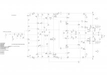
Have taken the hint. Attached is my first go at simplification. Removed HEC diamond buffer and changed the 2 pole shnuts to plain shunts. Also, have left the compensation as Damir posted.
How far to take the simplification? Could remove the input current sources and replace with resistors. The DC servo could be replaced by a FB Cap. Then the lower voltage rails for the front end are redundant. Then the cascodes? Although I feel (no scientific basis just experimental suggestion) that cascoded drivers aid in stabilising mosfet ops.
Certainly made me think "what are the key features that must stay?". These are the key features I feel make the project what it is:
1) "CFA" front end
2) CMCL
3) HEC with IRFP240/9240
The rest are secondary.
Paul
Attachments
Update
Hello all,
Update on this project. Have been working on a prototype that is heavily based on Edmond Stuarts work (MCP/PMP).
Have taken David Zan's advice and simplified the design back to what I would consider it's core. And this what I have built. Very simialr to the schematic above.
This is has been built and is working. Not done any real testing on it except hook it up to a speaker and mp3 player. It works without oscillation and produces music.
The question is where to go from here? Was thinking of implementing Dadod's compensation and maybe adding the DC servo as I really don't like using the capacitor C8 which I have removed in the real circuit. Offset is minimal without it anyway. Or should I do more testing? Or both?
Any ideas would be very much appreciated. This is just a starting point...
Paul
Attachments
Last edited:
Hello all,
Update on this project. Have been working on a prototype that is heavily based on Edmond Stuarts work (MCP/PMP).
Have taken David Zan's advice and simplified the design back to what I would consider it's core. And this what I have built. Very simialr to the schematic above.
This is has been built and is working. Not done any real testing on it except hook it up to a speaker and mp3 player. It works without oscillation and produces music.
The question is where to go from here? Was thinking of implementing Dadod's compensation and maybe adding the DC servo as I really don't like using the capacitor C8 which I have removed in the real circuit. Offset is minimal without it anyway. Or should I do more testing? Or both?
Any ideas would be very much appreciated. This is just a starting point...
Paul
Hi Paul, my suggestions:
Use input CCS, it lowers THD, not so good simplification replacing it with resistor.
Use DC servo, I my experience with GainWire mk2 preamp you can't control DC offset without it.
Do't use D3 and D4, it is worst way to get good clipping. Non linear diode capacitance added to nonlinear VAS Cob increases THD, use Baker clamp instead.
By the way how is going with your GainWire?
Damir
Hi Damir,
Thank you for your suggestions. Agree with you about the CCS at the input. Was thinking of using an LED based CCS. Trying to avoid any control loops. Have enough of them already in this design. Which CCS do you like the best?
DC servo is also my favourite option.
Will give the Baker clamps a go. I don't like D3, D4 either but it does give good clipping while being simple but then so are baker clamps.
Gainwire is currently in use attached to a dual AK4399 DAC as a headphone amp. It is lovely. Sony in ear headphones have no right to sound so good.
You have done a wonderful job on that design!!Paul
- Status
- This old topic is closed. If you want to reopen this topic, contact a moderator using the "Report Post" button.
- Home
- Amplifiers
- Solid State
- CFA Amp with CMCL and HEC Output Stage