Has anyone used the OPA1678 (dual-channel) or OPA1679 (quad-channel)? If so, how do they sound and how do they measure in ADC and DAC applications?
They are rated 4.5-nV/√Hz and 0.0001% THD but importantly they are 2 mA per channel (not 5mA).
There exist lower THD and lower noise super opamps but in some heat and current constrained applications I wonder if something like the OPA1678 might be much lower THD than stock and perhaps also better sounding? I am using interfaces that come with NJM2068, NE5532 and TL074 stock. (Digidesign and E-MU.) I did a test, for example, with upgrading a CS4398 DAC from NE5532 to LM4562NA and then OPA2134. The OPA2134 and LM4562NA measured almost identically but both above NE5532. OPA2134 measured the best. Perhaps OPA1678 will also not be the bottle neck and perhaps will measure similarly to OPA2134 or LM4562NA. And I would like to know what people think of the OPA1678 sound signature in DAC filter applications.
I ask since I am in the process of figuring out what to do with the TL074 in the Digidesign 003 rack. The OPA1679 (quad-channel) is one possibility as is the OPA4134. Also my E-MU 1616m is basically a little oven (half rack) with two PCB face to face with very little useful ventilation. So maybe OPA1678 is a suitable experiment for the E-MU.
The opa1678 is a nice little gem, I'm using them on the dam1021, it's a cmos opamp much like the opa1656, but a little slower and low power at 2mA/ch, and for those where cost matter, it's cheap at USD 0.22 each (qty 1K)
As some might have noticed, I really like TI new cmos opamps....
Last edited:

At $1.11 (qty 10) the quad OPA1678 might be a candidate to upgrade the TL074 in my Digidesign 003 rack (in the mic preamps). Others have used OPA4134.
That OPA1679 is INDEED a little gem! I hadn't noticed it before, but it definitely looks like a winner. SOIC-14s @ $1.11 ea. qty10; 9V/uSec;-120 THD; 4.5nV√Hz, and almost R-R output, all at 2mA. The 2134/4134 prices have gone through the roof and are 6x as much!
Last edited:
I think I will be trying the OPA1679 on my next Mouser order.
What about AD823? Should I stick with OPA2134? I ask since the AD823 is in a little ES9028Q2M board I have and I am pleasantly surprised how good that one sounded.
Does anyone have a guess what is inside the package of the Ebay and Aliexpress OPA2134? They measure much like LM4562NA in my CS4398, but they also measure as FET input and < 0.5 mV offset. They measured 0.35 mV offset with 10MOhm in the non-inverting input to ground, so some sort of FET. I wonder if they happen to be genuine. (I added 10 to an order for the fun of it, not expecting much. But they might be real. The NE5532 from the same order don't work properly and must be UTC or JRC 4558 or something like that. Noise was higher than Ti NE5532. Distortion was too high also. It was a deliberate experiment and I was expecting fakes. I tested them at 6kHz and compared with known genuine NE5532, LM4562, JRC4580, TL072.)
Last edited:
I can't imagine that low order distortion (both H2 and H3) sounding unmusical - check out image 4+5 in post #2
for me only high order THD components sounding unmusical - check out and compare measurements of test reviews from various models in stereophile mentioned in post #2.
They only integrate well when looking at a single tone signal and produce tones an octave above and an octave plus a fifth above.
But AFAIK the same mechanism produces intermodulation distortion even when looking at a two tone signal. And these imd products are very likely not musically related to the original tones. So IMHO any harmonic distortion products are undesirable for the best possible reproduction, including also k2 and k3.
That's surely true. But: the less tones an instrument produces, the less chance for intermodulation. And it cannot intermodulate with tones from other instruments.
In music reproduction, especially in more complex mixes, all the instruments have been combined to a single signal with a wide range of frequencies. Some of them not musically related at all, especially transient-like signals, drums for example or noise-like signals like cymbal hits. Such a signal with a very broad and complex spectrum gives much more opportunity for unmusical imd to occur.
IMO that's the reason for "girl and guitar"-like songs still sounding pleasing with equipment that produces high levels of k2 and k3. Not so many chances for unmusical imd products to be produced. Would be interesting to compare a hard rock mix on that kind of equipment...
Knowing some very good professional high end analog audio designers, I can say for those particular designers that when 2nd and or 3rd are allowed to exist it is not something that was done for intentional effect (not done to make an 'effects box'). Its because the amplifier is judged to sound best overall in a particular design state. Its an optimization problem that involves more than just minimizing HD and noise (perhaps to the astonishment of some AP users).
To put it in more theoretical terms, a good sounding amplifier is often the product of design that tries to make the amp as linear as possible without any global feedback. Then feedback can be applied for some further improvement, but my designer friends don't like the sound of too much feedback (and they don't like it despite being familiar with Bruno Putzey's claim about just needing even more feedback).
To put it in more theoretical terms, a good sounding amplifier is often the product of design that tries to make the amp as linear as possible without any global feedback. Then feedback can be applied for some further improvement, but my designer friends don't like the sound of too much feedback (and they don't like it despite being familiar with Bruno Putzey's claim about just needing even more feedback).
Last edited:
There's no solid technical or theoretical reason for any of this to be true, it's all entertainment as Nelson says. After all is it any different than folks that prefer DAC's that "remove" the reverb tails. I assume we still are not allowed to ask for any unbiased DBT results, for the usual reasons or course. BTW the AP is just a measurement instrument, why would anyone be astonished by its measurements.
Last edited:
My 1616m loopbacks were best around -10 dBFS from the DAC. (REW generator set for -10 dBFS.)
So you replaced all the op-amps, inputs and outputs? Did you recap the 1820m first?
I just recapped 2 channels of my older 1820m with LM4562 in it and tested the result before moving on to do the rest. Very interesting results, and thank you once again for pointing out what you found with respect to caps in yours; these charts quantify what old electrolytics can do. They represent loopback both before and after a complete recap in both ADC and DAC (and PS section). The charts are actually for two different channels (1 - recapped, 3 - old caps). Channel 1 has always shown a bit higher harmonics than all the others and its before state was slightly worse than the "before" posted below.
Attachments


Last edited:
Glad it helped. I am guessing that the removed FILT caps measured pretty badly after removal.
Which channel is ASIO 7 physically? And 8? (I ask since I am wondering why the full scale/peak signal is different. One near -3 dBFS and one near 0 dBFS.)
After I replaced all the 47uF 16V blocking caps all my channels measured at almost identical levels. (They were all over the place before replacement.)
Last edited:
Glad it helped. I am guessing that the removed FILT caps measured pretty badly after removal.
Which channel is ASIO 7 physically? And 8? (I ask since I am wondering why the full scale/peak signal is different. One near -3 dBFS and one near 0 dBFS.)
After I replaced all the 47uF 16V blocking caps all my channels measured at almost identical levels. (They were all over the place before replacement.)
The ASIO is just how I have it routed in the mixer to do the test of DOC I/O 1 and DOC I/O 2.
The first two charts are for -3dBfs and the software labeled it -3.77 and -3.68. The second two charts are for -.1dBfs and got labeled -.87...
I recapped with Panasonic using FC as first choice when possible and M when not available in FC. The DACs turned out to be all 105 degree M. The ADC is mostly 105 degree M. I did FS for power (10K hrs).
The subjective sound is incredible. I still have some channels of 2068 with old caps, so can A/B and the difference is shocking in a very good way. It would cost some serious cash to get 8 channels of this quality.
Also FWIW, the 1820m with OPA1656 in it hasn't been recapped yet but they chart to still be reasonably healthy. The subjective SQ of DAC in that one is even better. I'd like to put 1656 in this old one but one of the pads began to break lose from the board while attempting to remove a 4562, so not going to risk it... It sounds great with 4562, but the 1656 is a a bit better IMO. Both are getting a small external centrifugal fan to force ambient air thru them. And I'll be using the 1212m card for daily mixing sessions since it can get plenty of cooling and all I need is a stereo out for that...
Last edited:
The 1820 and 1616 have ceramic (likely X7R) surface rail caps but I have not removed any to measure the value. I don't know about feedback caps as I have not traced out the circuit that E-MU used with the original NJM2068. (Since 2068 is a dual and 2x34 is 68 I wonder if the NJM2068 is intended to be a souped up dual 5534?)
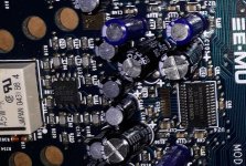
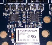
I don't know if anyone has traced out the E-MU circuits. Attached is the CS4398 DAC filter (first, lots of SMD caps) and second is the balanced output driver (no extra SMD caps).
The EIA-96 SMD resistor code 39B stands for 2.49 kΩ / 1%
The EIA-96 SMD resistor code 68B stands for 4.99 kΩ / 1%
The 3 digit SMD resistor code 561 stands for 560 Ω.
I wonder if there is any value in adding 10uF electrolytic bypass caps across the ceramic op-amp rail bypass capacitors? Or rail to rail directly on the op-amp pins?
Attachments
Last edited:
I don't know if anyone has traced out the E-MU circuits. Attached is the CS4398 DAC filter (first, lots of SMD caps) and second is the balanced output driver (no extra SMD caps).
I haven't seen anything on the net... But FWIW, products like the 1820m and 1616m are usually based on the chip maker's reference design. For the CS4398 you can find it in their product eval board datasheet:
https://statics.cirrus.com/pubs/rdDatasheet/CDB4398.pdf
I've often found ref designs useful for "educated guess tracing" a section. 😉
Just a couple words of caution regarding trying to evaluate op-amp swaps with a simple loop-back on the interface being modified:
In the attached example the first two images are a CS4392 DAC with OPA2134 op-amp for the filter. The second two images are the other channel of the same DAC chip and that other channel has the stock NE5532 op-amp for the filter.
This is inside a modified Digidesign 003 rack with improvements for clock jitter and noise on both the analog and digital power supplies.
The measurements are being made with a nearly 90 dB 1kHz notch filter. (Made as stable as I can make it so far.) From this experiment I am finding that it is very hard to measure the difference between op-amps on modern ("good") DACs/interfaces because the distortion is so low that most interfaces will have trouble measuring the results. Not only is the ADC a limiting factor but noise is also a problem. I am using 1M FFT points and 32 averages. For very good op-amps the DAC, ADC and power supplies seem to be greater limiting factors than the op-amp I am trying to evaluate. For example, using a notch filter the stock humble NE5532 looks far better than when initially evaluated without a notch filter.
So if you are just doing a loop-back test without notch filters or other fancy test equipment you might not be able to measure the impact of the op-amp swap.
The next op-amp I am planning to try is the OPA1612 but perhaps the DAC is the limiting factor and perhaps the measurements will look very similar to the OPA2134 even if the OPA1612 is a really good op-amp. At this point noise and ultra low noise supplies might be the last area I should put more effort into for this interface.
Note that the software is taking 1kHz as "0" insertion loss (it is actually near -90 dB insertion loss) so the levels end up (mathematically) being reported as very low.
Attachments


Last edited:
So if you are just doing a loop-back test without notch filters or other fancy test equipment you might not be able to measure the impact of the op-amp swap.
I agree though I am able to see minute differences in trend between OPA1656 and LM4562 since I have 8 channels each to measure. But then the 2068 measures in the same league in this application, but SQ wise not in the same league at all imo.
IMO, any modern OPA spec'd for audio use is going to be a sonic upgrade for this application. I can attest the 1656 along with Panasonic 105 degree FC in signal path wherever possible and Panasonic M where FC isn't an option (i.e. the 470uF 6.3v on the ADC), is a major sonic upgrade over a healthy stock unit. Plenty of great alternatives out there I'm sure and some may even be marginally preferable for all I know, but this combo is very good imo.
As for the thermal issues, I have a pile of these coming to put on the opamps along with fans to force ambient air thru the case. Anything to try to keep from cooking all of these new electrolytic caps...but then the pulls are closing in on 18 yrs old, so was past time for them to be replaced, cooked or otherwise...amazing a piece of gear that old can be restored/upgraded to provide the SQ these can provide.
Last edited:
I do hope the sound quality improves much more than the FFTs.
I repeated my measurements by creating a better calibration file and also using the manual fundamental feature in REW. More details can be found here: Howto - Distortion Measurements with REW
The new results of the CS4392 with stock NE5532 output filter is attached as image 1. CS4392 with stock OPA2134 output filter is attached as image 2 and in percent as image 3.
Now the results are pretty much identical which is not what I was expecting. I guess I am measuring the CS4392 chip more than the op-amps. (The measurements are of two halves of the same DAC chip, one half with NE5532 and the other half with OPA2134.) Before building the notch filters I was mostly measuring my ADC (I think). At least with the notch filter I can get beyond the ADC distortion limitations. Perhaps adding an LNA will help. The red line in the images is the response of the notch filter.
Attachments


Last edited:
I do hope the sound quality improves much more than the FFTs.
...
I guess I am measuring the CS4392 chip more than the op-amps...
I just did one stereo pair and auditioned to make sure it was worth the effort (even though the money for parts was already spent) before committing to doing the whole job. When I did the first one years ago the SQ improvement of the single stereo pair definitely made it easier to spend the amount of time required to do the rest. And same for recapping two 1820m and a 1212m (already finished) now. With quality opamps and caps they aren't going to be the weak link, no matter what you have for microphones, preamps and monitors. I couldn't really say that when they were stock despite good measurements.
- Home
- Amplifiers
- Solid State
- Choosing of best sounding OP AMPs for the lowest possible THD+N -really the best Way?