Thanks for posting the reference text. Have you noticed, in Electronics World Fig. 5, the reversal of the OPA604 inputs ? Global feedback is positive instead of negative. April fool's joke maybe ?Remember: only for personal and study use, NOT for commercial use...
Why so complicated?
Real SuperA mode amp:
??-2012 ???????? - ????????? ???????? Nataly - ????? ?? ????????????????
It's not JVC VC5022 release, but it works very good & stable.
Real SuperA mode amp:
??-2012 ???????? - ????????? ???????? Nataly - ????? ?? ????????????????
It's not JVC VC5022 release, but it works very good & stable.
Just found this one:
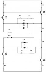
"a new Class-AB design (Wim de Jager - Electronics World December 1999)"
There is no Voltage Amplifier Stage (VAS) as such.
The positive and negative Darlington output devices (Tr9, Tr11, Tr10, Tr12) provide a huge current amplification, as they are wired in common emitter.
Assuming Tr1 collector current equals Tr3 collector current,
hence no audio current,
and only some quiescent current,
the more Tr8 conducts, the more we get current :
- sinked from Tr9 base, hence sourced to the load by Tr11 collector
- sourced to Tr10 base, hence sinked from the load by Tr12 collector
Tr14 acts as constant current sink, say 4 mA.
Say the amplifier is providing a significant positive output voltage, hence a significant positive current to the load.
Assuming the whole circuit is working well, Tr11 base voltage will go down (not a lot), thanks to Tr1 sinking audio current from Tr9 base, whose emitter is sinking audio current from Tr11 base.
Tr6 buffers Tr11 base voltage, while causing one Vbe drop.
Tr7 wired as a diode, causes another Vbe drop.
Tr8 buffers such voltage, while causing one Vbe increase.
Tr9 base is thus forced by feedback, to one Vbe less than Tr11 base voltage.
Such is the interlock.
One should consider such interlock, as a guarantee that whatever happens, Tr11 will never cease conducting. This looks like a "non-switching" Class-AB.
However this is not the full story yet.
Comes the question : what's Tr8 collector current ?
One must remember that Tr7 emitter is one Vbe less than Tr11, while Tr8 emitter is also one Vbe less than Tr11.
If we accept the idea that Tr7 and Tr8 are connected to same emitter voltages, we should consider Tr7 and Tr8 as a current mirror arrangement, meaning that Tr8 collector current is supposed to be the same as Tr7 collector current. Unfortunately, this is a gross approximation.
Tr7 emitter is connected to one Vbe less than Tr11 base voltage.
While Tr8 emitter voltage is a buffered (one Vbe increase) version of Tr7 base voltage.
That's the subtlety.
One cannot say that Tr8 collector current is a mirror of Tr7 collector current.
Tr8 emitter imposes a voltage on Tr9 base, and we still don't know what's Tr8 collector current.
Tr7 and Tr8 experience dissimilar collector voltages.
Tr7 collector voltage is highly positive : +25 volt less three Vbe drops.
Tr8 collector voltage is highly negative : - 25 volt plus two Vbe drops.
This is another reason forcing us to consider that Tr7 and Tr8 don't act as current mirrors.
Obviously, Tr8 collector current is much less than Tr7 collector current.
Let's look what would happen, in case Tr8 collector current would be 4 mA, same as Tr7 collector current, same as Tr14 collector current.
Tr10 base current would also be 4 mA. Tr10 collector current would be 200 mA (assuming beta Tr10 = 50). Tr12 collector current would be huge, say 10 amp (assuming beta Tr12 = 50). Self destruction ...
Let's thus consider Tr8 as a common base arrangement, imposing an emitter voltage. Tr8 emitter gets its current from two locations :
- the differential input stage (Tr3 adding current, Tr1 removing current)
- Tr9 base (as small extra)
As soon as Tr8 starts conducting, Tr9 base gets fed, Tr9 collector gets fed (say Beta = 50), Tr11 base gets fed, which causes more current flowing into Tr11 emitter and collector (say Beta = 50). So, in case Tr8 conducts 100 µA, Tr11 could conduct as high as 250 mA.
And, we have the same pattern in the negative drive.
As soon as Tr8 starts conducting, Tr10 base gets fed, Tr10 emitter gets fed (say Beta = 50), Tr12 base gets fed, which causes more current flowing into Tr12 emitter and collector (say Beta = 50). So, in case Tr8 conducts 100 µA, Tr12 could conduct as high as 250 mA. Which is a lot.
Now, look what's happening if you reduce Tr14 current from 4.0 mA to 3.9 mA, while considering that Tr11 and Tr12 still conduct 250 mA in first instance.
Tr7 Vbe and Tr6 Vbe will decrease. Consequently, Tr8 Vbe will decrease. Consequently, you force Tr8 to conduct less. Consequently, Tr11 and Tr12 will conduct less. Now we better realize the role of Tr8, governing Tr11 and Tr12 collector currents.
How to generate a fast strong positive output, as audio ?
Tr1 is there, able to sink current from Tr9 base, which is going to be amplified by 2,500 as see before.
How to generate a fast strong negative output, as audio ?
Tr3 is there, able to source current into Tr8 emitter, that's actually flowing into Tr10 base, which is going to be amplified by 2,500 as see before.
It seems that such circuit obeys two kinds of feedback :
- a strong negative feedback, dealing with the differential voltage amplification and the 2,500 current amplification, which is dealing with audio,
- a weak feedback, dealing with the quiescent current
Not everything looks 100% clear to me.
Can somebody better explain such circuit ?
Regards,
Steph
Attachments
-
 A new Class-AB design (Wim de Jager - Electronics World December 1999).1.jpg481.8 KB · Views: 553
 -
 A new Class-AB design (Wim de Jager - Electronics World December 1999).2.jpg348 KB · Views: 539
 -
 A new Class-AB design (Wim de Jager - Electronics World December 1999).3.jpg370.4 KB · Views: 535
 -
 A new Class-AB design (Wim de Jager - Electronics World December 1999).4.jpg341.2 KB · Views: 538
 -
 A new Class-AB design (Wim de Jager - Electronics World December 1999).5.jpg428.5 KB · Views: 527
 -
 A new Class-AB design (Wim de Jager - Electronics World December 1999).6.jpg455.2 KB · Views: 313
Last edited:
Kenwood's version of non-switching outputs from the KR-7XX line from the early 80's.
Attachments

Last edited:
Member
Joined 2009
Paid Member
Ed is a very smart and very nice guy, never realized he had published this project all those years ago along with a few others I know.
Last edited:
This was my variant back in 1994, I still use it every day. The class-AB bias loop forces the currents through the output transistors to have an exp(-R IDQ1/Vt) + exp(-R IDQ2/Vt) = constant relation.
I sized it such that the quiescent current is about 100 mA and the current through one side when the other current gets large is about 50 mA. That was just a compromise between quiescent power and variations of the small-signal parameters of the BUZ10 output transistors; there is no distortion minimum like in conventional amplifiers as far as I know.
With more modern power MOSFETs you would have to carefully check the SOAR curves for any signs of Spirito instability (= thermal second breakdown). High voltage power MOSFETs are often still usable for amplifier applications, provided you stay well below the maximum voltage rating.
Attachments
Last edited:
Member
Joined 2009
Paid Member
Ed? what projects?
Ed van Tuyl (article posted by Steph) at the time of the article he was at the U of Twente. They have an active audio lab there, lots of fun stuff.
The Jager circuit is a special case of ingenuity. Tr9 and Tr8 are the transistors responsible for switching the output stage. TR5/6/7 act as a shunt regulator which keeps Tr8/9 biased.
At negative output, Tr8 turns on and drives the negative half of the output stage. For positive output, Tr9 turns on and drives the positive half of the output stage.
What makes this confusing is the asymmetry of the circuit. Tr11 gets 1 driver, but Tr12 gets 2? The key here is that Tr10 has no B-E resistor. When a BJT collector drives a BJT base without a B-E resistor, they function mathematically like a single transistor. Very roughly, at AC, Vbe(Tr8)=Vbe(Tr10)=Vbe(Tr12). And Vbe(Tr11)=Vbe(Tr9). So when Tr8 and Tr9 are switching, the behavior is symmetrical even though Tr8 is only biased in the hundreds of uA.
This is the result of the scalability of BJTs. No matter what bias current, a 50% change in Ic will always result in about an 18mV change in Vbe. So because the Ib of the output transistor is proportional to it's Ic, both it and it's driver experience the same relative change in Ic, and thus the same change in Vbe.
It looks like an asymmetrical version of the Monticelli class-AB stage, but not exactly. See https://www.google.com/patents/US4570128 for the Monticelli patent (which has long passed its due by date).
Last edited:
There's also a Thesis by L Krishnan (2011) with analysis and comparison to another Class-AB bias method, it's here .It looks like an asymmetrical version of the Monticelli class-AB stage, but not exactly. See https://www.google.com/patents/US4570128 for the Monticelli patent (which has long passed its due by date).
There's also been some simulations done recently of the de Jager amp, eg here
Member
Joined 2009
Paid Member
- Status
- Not open for further replies.
- Home
- Amplifiers
- Solid State
- Class AB Soft Non-Switching