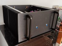
It's alive! Everything worked right from the start. Today I finished the build. In the past I thought of it as an Aleph40 build. But it will be more of an Aleph35+ because it seems to run a bit hotter then expected in the 5U 400 Enclosure. To be fair I think the 5U 400 is a good match if you want to build a cool running standard Aleph 30. I could have known this before, there are a lot of helpful comments about the ability to dissipate heat of different modushop enclosures.
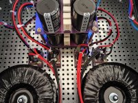
My V8 CRCRC PSU ends up at (only) 27.6V per rail when a current of 2.7A is drawn. I suspect that the 2x22V 400VA Toroidy.pl donuts are not stiff enough or the CRCRC drops more volts than I expected. I would love to be able to compare my donuts with Antek ones.. But for now it that doesn't matter, because for the moment I am limited by the heat dissipation anyways. So a Mighty Babysitter is needed.. Or maybe liquid cooling?
The first listening test was pleasing. There is no trace of residual hum in this dual-mono build. I guess it's because of the CRCRC PSU plus double the filter capacitance compared to the F5 T PSU in my old A30 build (built with the same type of capacitors). It's hard to tell the differences between the A35+ and my "old" A30 build. And it will be even harder to tell where the differences come from, because so many details are different in the new build:
Will I end up buying a second 5U 400 enclosure to build two Aleph 60 monos? Stay tuned, time will tell 😂
My V8 CRCRC PSU ends up at (only) 27.6V per rail when a current of 2.7A is drawn. I suspect that the 2x22V 400VA Toroidy.pl donuts are not stiff enough or the CRCRC drops more volts than I expected. I would love to be able to compare my donuts with Antek ones.. But for now it that doesn't matter, because for the moment I am limited by the heat dissipation anyways. So a Mighty Babysitter is needed.. Or maybe liquid cooling?
The first listening test was pleasing. There is no trace of residual hum in this dual-mono build. I guess it's because of the CRCRC PSU plus double the filter capacitance compared to the F5 T PSU in my old A30 build (built with the same type of capacitors). It's hard to tell the differences between the A35+ and my "old" A30 build. And it will be even harder to tell where the differences come from, because so many details are different in the new build:
- a dual mono PSU with two transformers
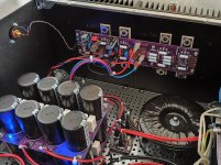
- a CRCRC filter for each rail, instead of a shared CRC Filter
- local reservoir / decoupling capacitors on the new revision of the PCB
- a 1uF input capacitor instead of 4,7 uF in the old build
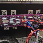
- Harris / Fairchild 9610s instead of Vishay in the old build
- 2 additional MOSFETS per channel
- source resistors and output resistors of 0.68 ohm instead of 0.47 ohm in the A30 build
- current limiter set to much higher value
- almost double the heat dissipation compared to standard A30
Will I end up buying a second 5U 400 enclosure to build two Aleph 60 monos? Stay tuned, time will tell 😂
back-up P3 to 0 Ohms, increase R19 for 40-50K
then re-bias
say that new value for R13=68K is pretty much OK for your case
So I wound up using 52.3K resistors at R19. I am now able to get it up to 3 amps after it has fully warmed up, although I do have to crank P3 all the way to get it there.
I did not change R13. Is there any reason to given I'm able to get the proper current with just R19 changed?
I also wound up changing the fuses to 5A because it does draw 5A very briefly when I first turn the amps on.
Thanks,
Alan
@aljordan
when I wrote :
"
back-up P3 to 0 Ohms, increase R19 for 40-50K
then re-bias
say that new value for R13=68K is pretty much OK for your case"
that "R13" was a typo - I meant R19 of course
now, some more tweaking
measure AC gain of Aleph CCS
that's nothing else - feed 1KHz signal (dummy load at output) , watt or so, then measure AC across upper source resistor group
then measure AC across lower source resistors group
if these two AC figures are the same, then Aleph CCS gain is at 50%
if you're happy with A. AC gain you have, no need for change
if you want to alter it, alter (accordingly ) value of P2 - higher ohmic value, lesser A. AC gain, and lower ohmic value, higher A. AC gain
that will alter slightly THD Spectra of amp itself
What (general) values are you talking about? Sounds silly to ask, but how far are they off? You're not measuring them in-circuit are you? What precision/accuracy are you expecting? Do you want to pay to have it calibrated semi-annually?
A resistor in the 50K range is about 1% low. It isn't a problem for doing regular checking of resistors before populating boards. My post was really in question to AddiDub posting that he measures pots to possibly change them out to regular resistors, which got me thinking about the accuracy needed to do that. I am pretty both my meters are not calibratable (a very old but rather nice Radio Shack meter, and a Klein MM700.
Congrats! How do they sound?
They sound fabulous! My tougher-to-drive speakers sound very good. Beautiful detail combined with a warmth and good bass control. Excellent imaging. Better results than I was hoping for. Many years ago I used to drive these speakers with XA 100.5's, which sounded very good but did not really control the bass drivers well enough. The Aleph 2's are controlling the bass drivers, which may be due to other system changes as well, but I am very happy with the results.
Well, it was something like 3 in the morning your timethat "R13" was a typo - I meant R19 of course
")
I will recheck the AC gain once I am done listening for the day. Thanks again for your help.
it's easy enough for you just to compare simplest reading on 1KHz and, say, 400-500Hz
that will give you proper info about your DMM
besides that, you're not chasing absolute values, relative ones are good enough - meaning - if there is some error, it will be same on two relatively close values
that will give you proper info about your DMM
besides that, you're not chasing absolute values, relative ones are good enough - meaning - if there is some error, it will be same on two relatively close values
You want a completely speculative answer? Try adding a resistor to ground at the amp input. It will share current with the input device and increase input Z.Hello again,
The (single ended) input impedance of the Aleph 2 is 10Kohm. The single ended input impedance of the Aleph 60 is 47K. Is it possible to raise the input impedance of the Aleph 2 to that of the Aleph 60 without causing harm to the performance of the circuit?
On the V8 CRCRC Mono PSU board R11/12 are the LED drop resistors. The "rule of thumb" is to use 1k per volt of rail voltage. For example, with +/- 24V rails, use a 24k resistor. More for dimmer LED. Only have a spare 26k in your box of parts? That's fine, too. It doesn't need to be exact.Hi,
just a short and maybe dumb question to the psu: are the resistors R11 und R12 with the LED in series bleeder resistors?
R9 and R10 are the bleeder resistors on that board. The 2K2's.
Many thanks for the clarification.On the V8 CRCRC Mono PSU board R11/12 are the LED drop resistors. The "rule of thumb" is to use 1k per volt of rail voltage. For example, with +/- 24V rails, use a 24k resistor. More for dimmer LED. Only have a spare 26k in your box of parts? That's fine, too. It doesn't need to be exact.
R9 and R10 are the bleeder resistors on that board. The 2K2's.
I knew that they have the LED drop function but I thought they serve as bleeder too.
Stupid me
Not stupid at all!Many thanks for the clarification.
I knew that they have the LED drop function but I thought they serve as bleeder too.
Stupid me
In reality, they do have a LITTLE bleeder function. But 2K2 has main bleeder function. "path of least resistance" - literally.
Today I finally adjusted the AC current gain to 50% on both channels. I used a 4-ohm load. After that I let the Amp warm up a bit. A quick check with the oscilloscope and signal generator (1kHz) showed that the Aleph 30+ is able to deliver at least 15V-16V RMS clean into the 4-ohm resistive load. That means something between 56W to 64W into 4 ohm. With my other Aleph 30 build I achieved about 35 Watts into a 4 ohm resistive load (23.3V / 2.2A).
Rail Voltage: 27,6 V
Quiescent Current: 2.7A
Total dissipation per channel: 150W
Heatsink temperature 5U 400: insanely hot
Sound: insanely good
No scope pics where made (yet) so I attached some pictures of the build.
Rail Voltage: 27,6 V
Quiescent Current: 2.7A
Total dissipation per channel: 150W
Heatsink temperature 5U 400: insanely hot
Sound: insanely good
No scope pics where made (yet) so I attached some pictures of the build.
Attachments
- Home
- Amplifiers
- Pass Labs
- Classic Aleph Amplifier for Modern UMS Chassis Builder's Thread