Hi all,
just want to post a basic (old fashioned) signal generator.

Frequency range: 1Hz - 150kHz (possible to run up to 450kHz)
Output amplitude: +-5V
Reduced basic design, beside the bit uncommon sine-shaper. An quad opamp (LMH6644) is mainly doing all the magic, an LM386 is used as a charge-pump to generate the negative supply voltage. Resulting output ripple on the V- rail is about 2mVpp after the LM337. The output swing may need a bit of compensation, will see.


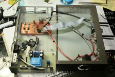
A first prototype (with dual transformer supply):


The new one will be 50x50mm in size.

just want to post a basic (old fashioned) signal generator.
Frequency range: 1Hz - 150kHz (possible to run up to 450kHz)
Output amplitude: +-5V
Reduced basic design, beside the bit uncommon sine-shaper. An quad opamp (LMH6644) is mainly doing all the magic, an LM386 is used as a charge-pump to generate the negative supply voltage. Resulting output ripple on the V- rail is about 2mVpp after the LM337. The output swing may need a bit of compensation, will see.
A first prototype (with dual transformer supply):
The new one will be 50x50mm in size.
Attachments
-
 Siggen_5050_060914_1137.png41.1 KB · Views: 1,590
 -
 1857_1409920627_LM386_Square_Comparsion_Inductor_Comp_3u.png36.9 KB · Views: 1,320
 -
 1857_IMG_8003.JPG287 KB · Views: 1,275
 -
 1857_IMG_8174.JPG530.9 KB · Views: 1,287
 -
 1857_1409742493_Siggen_5050_.jpg80.5 KB · Views: 1,234
 -
 1857_1409920814_LM386_Square_Comparsion_Inductor_Comp_3u_power.png9.4 KB · Views: 1,345
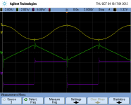
Some measurements on the prototype shown next (Don't mind the distorted square-wave at low frequencies, the scope-inputs where AC-coupled). The distortion at higher frequencies (100kHz+) comes from limited slew-rate and missing output-compensation. Will get this fixed.
🙂
1Hz:

10Hz:

50Hz:

100Hz:

1kHz:

5kHz:

10kHz:

20kHz:

50kHz:

100kHz:

🙂
1Hz:
10Hz:
50Hz:
100Hz:
1kHz:
5kHz:
10kHz:
20kHz:
50kHz:
100kHz:
Attachments
-
 1857_Siggen_100kHz.png36.2 KB · Views: 988
 -
 1857_Siggen_50kHz.png34.3 KB · Views: 1,001
 -
 1857_Siggen_20kHz.png32.9 KB · Views: 1,024
 -
 1857_Siggen_10kHz.png32.4 KB · Views: 1,050
 -
 1857_Siggen_5kHz.png37.7 KB · Views: 1,076
 -
 1857_Siggen_1kHz.png31.4 KB · Views: 1,122
 -
 1857_Siggen_100Hz.png32.2 KB · Views: 1,107
 -
 1857_Siggen_50Hz.png32.8 KB · Views: 1,111
 -
 1857_Siggen_10Hz.png33.7 KB · Views: 1,119
 -
 1857_Siggen_1Hz.png35.4 KB · Views: 1,113
If you are open to criticism I would say that this design is way below from what I would describe as basic sound generator.
I would suggest you to pause this project and to seek for an more advanced circuitry in which you will finally instal in your metallic box.
I do understand that this is your training project, if you are not interested to improve it regarding specifications, just have fun and ignore my message.
I would suggest you to pause this project and to seek for an more advanced circuitry in which you will finally instal in your metallic box.
I do understand that this is your training project, if you are not interested to improve it regarding specifications, just have fun and ignore my message.
Looks very nice. Triangle waves really don't do much for basic measurements as an FFT analyzer even one based on a PC will show more detail. But as you use it for the input to the sine shaper the output is free.
Square waves are nice but for audio a good clean square wave doesn't need to go much above 20khz.
The important issue is the sine wave output level should not vary with frequency. It is also useful to go above 200khz. I would try a 390pf capacitor across R24 to clean up the triangle switch noise in the sine output.
So very nicely done.
You may wish to build a low distortion sine wave source for distortion measurements. A good low distortion oscillator should be cleaner than a digital version.
Last edited:
@doctormord,
Nice little project. I like to see how to go from
something larger to smaller the way you are demonstrating.
For some this might be pretty simple or no big deal.
It doesn't matter, to me I am here to learn and I like to
see how things are done.
@kiriakos,
If design is much to simple, then what should be included in a
CLASSIC sound generator?
Is that different than a BASIC sound generator.
It could even be more basic with only
a sine & square wave....or just the sine wave.
How many functions should a basic sound generator have?
and at what level? Basic for Test and Measurement? or
basic for hobbiest? or basic for DIYers? or basic for lab?
Ah ha, I would imagine that that is why there are design parameters?
Kinda like building a house...one room with an out house
or
4 bedrooms, 3-1/2 bathrooms, 1 kitchen, 1 dining room, 1 living room,
1 mud room, 1 multimedia room, 2 work rooms, 4 car garage,
hobby room, tool shed, storage room, split HVAC system,
multi phase electrical drops, mechanical room, and dog house,
window to the hot babe is extra.
Last edited:
@kiriakos,
If design is much to simple, then what should be included in a
CLASSIC sound generator? ........Ah ha, I would imagine that that is why there are design parameters?
Kinda like building a house...
Yes kinda, like building a house. 🙂
Even today there is small availability regarding old stock of one successful all-in-one function generator chip of the past, in a price of 50-60$ which all additional requirements for getting the most of it, are additional output filters and one impedance selector circuit for 50 or 600Ohm output.
This is the basic design of a good generator which it can fully expand regarding potentials by adding to it Duty-cycle and FM/ AM modulation.
Yes the wheel has been invented before us and by other people, and therefore if the cost of your DIY project does restrict you below the 150 EUR mark, you may build the best analog generator or spend few more, and buy an used PHILIPS PM5134
..
Last edited:
If you are open to criticism I would say that this design is way below from what I would describe as basic sound generator.
I would suggest you to pause this project and to seek for an more advanced circuitry in which you will finally instal in your metallic box.
I do understand that this is your training project, if you are not interested to improve it regarding specifications, just have fun and ignore my message.
Hi Kriakos,
thanks for your reply. What problems do you see with this circuit? The power-supply-part could be more simplified, with just some virtual-ground using another opamp.
Regards,
doc
The circuit-design is a derivation of a design done by a friend of mine.

This gives the following waveforms:

Specs are:
F-Range: 1Hz .. 200 kHz (1 Mhz with small errors)
Sine Distortion: < 1,5 %
My initial design in Multisim shows this (using LT1365):

This gives the following waveforms:
Specs are:
F-Range: 1Hz .. 200 kHz (1 Mhz with small errors)
Sine Distortion: < 1,5 %
My initial design in Multisim shows this (using LT1365):
Attachments


Hi Kiriakos,
thanks for your reply. What problems do you see with this circuit? The power-supply-part could be more simplified, with just some virtual-ground using another opamp.
Regards,
doc
For start lets say that when I am measuring the impedance of my generator by a multimeter it measure up as 50 Ohm or as 600 when is selected.
Your Oscilloscope is at 1G Ohm impedance, therefore there is no chance getting a measurement which will be considered as accepted by this setup.
Aight, that's what I meant. While tested, the scope inputs where AC-coupled by a mistake, resulting in wrong signal display for the square wave.
The transistored sine-shaper is meant to be less than 1% THD at 1-10khz. (Not high tech but nearly all sine-generators which are not fixed frequency and/or wien-configuration aren't any better, or needs much more effort)
It also is temperature/voltage self-stabilized.
The transistored sine-shaper is meant to be less than 1% THD at 1-10khz. (Not high tech but nearly all sine-generators which are not fixed frequency and/or wien-configuration aren't any better, or needs much more effort)
It also is temperature/voltage self-stabilized.
 I've pulled some posts from three different people that went beyond technical dispute into the personal. Please reread the forum rules.
 Feel free (and encouraged) to repost any technical content that was lost.
I made a writeup at my website to further explain, whats going on with this circuit. Feel free to help me with the translation. 🙂
Signal / frequency generator 1Hz-200kHz (sine, square, triangle) - #360customs
Signal / frequency generator 1Hz-200kHz (sine, square, triangle) - #360customs
- Status
- Not open for further replies.
- Home
- Design & Build
- Equipment & Tools
- Classic signal generator (1Hz-150kHz[250kHz]) Sine, Triangle, Square