My apology if this has been discussed and I shall be grateful if someone can point me to the right place for the answer, for I searched and did not find the answer that I am looking for.
For a +-35Vdc PSU:
What inductor value should I use? I know there is probably different preference but is there a general rule of thumb where I can start and do the tweaking from there.
Thank you.
For a +-35Vdc PSU:
- 2500VA transformer with 25Vac (50A) x 2 output
- total 100mF electrolytic capacitors
What inductor value should I use? I know there is probably different preference but is there a general rule of thumb where I can start and do the tweaking from there.
Thank you.
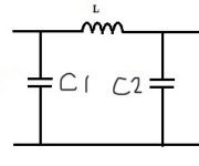
For attenuation factor of 1/216, L must be at least equal to 2160 x ZC at 100Hz. If ZC = 0.006 Ω for 50mF, 100Hz, then ZL = 216 x 0.006 = 1,296 ohms, and L = ZL / ( F x 6.28 ) = 1,296 / (100 x 6.18 ) = 0,002 Henrys or 2mH.
The frequency resonance, Fo, between L and the C2
Fo = 5,035 / sq.root (L x C)
where Fo = Hz, L = mH, and C = uF.
Fo here = 5,035 / s.rt (2 x 50000) = 15.9Hz, inside the audio band
Please check the maths because I'm not strong.
All information, formula and credits thanks to Patrick Turner R.I.P. attached PDF
Attachments
Last edited:

Thank you very much for the detailed explanation, calculations and PDF, although I must admit that the PDF is too complicated beyond my comprehension, but your simplified practical version is extremely useful.
Sorry if I didn’t make myself clear, the 100mF capacitors are 25mF x 4, 2 each for positive and negative VCC, I.E. C1 is 25mF and C2 is 25mF.
The ESR at 100Hz for each 25mF capacitor is 12mOhm.
For the ZC referred in your formula, should it be ZC of C1 and C2 combined?
For “The frequency resonance, Fo, between L and the C2”. Is this C2 same as my C2 = 25000uF?
What would be the preference for Fo, higher or lower or doesn’t matter as long as it is within audio band?
Thank you!
Attachments
If ZC = 0.006 Ω for 25mF, 100Hz, then ZL = 216 x 0.012 = 2,592 ohms, and L = ZL / ( F x 6.28 ) = 2,592 / (100 x 6.28 ) = 0,004 Henrys or 4mH.
The frequency resonance, Fo, between L and the C2
Fo = 5,035 / sq.root (L x C)
where Fo = Hz, L = mH, and C = uF.
Fo here = 5,035 / s.rt (2 x 25000) = 4.4Hz
N.B. bold numbers are part of formula.
As I understand:
1-ZC is the value of each capacitor not the sum.
2-Fo is the resonant frequency of the low pass filter formed by L & C2
3-Of course lower 20Hz that's the beggining of audio signal, sorry wroted inside audio signal the other post.
Don't forget the current/power of inductor/choke & when design the PSU also you have to count with choke/inductor DCR
Good lucky with your project & enjoy the trip as I do.
“ZC is the value of each capacitor not the sum.”
Is there any benefit if ZC1 > ZC2 (having two different capacitance values) or the other way around?
What if ZC1 is not equal to ZC2, when calculating the inductance required, should I use the value of ZC1 or ZC2?
Thank you for the clarification😊
Is there any benefit if ZC1 > ZC2 (having two different capacitance values) or the other way around?
What if ZC1 is not equal to ZC2, when calculating the inductance required, should I use the value of ZC1 or ZC2?
Thank you for the clarification😊
I use PSUDII to simulate all my PSU with great success.
https://www.duncanamps.com/psud2/download.html
https://www.duncanamps.com/psud2/download.html
Well if you use the PSUII simulator you can see how affect the ripple, all depends your target: you want a fast PSU or you like a overdamped PSU, it all depends your goal, etc.
If you use C1 small value you will have a fast PSU but can increase AC ripple, if you use a lot of capacitance in general become more slow, better use PSUDII so you can see as your own.
Of course the best PSU is with choke input.
If you use C1 small value you will have a fast PSU but can increase AC ripple, if you use a lot of capacitance in general become more slow, better use PSUDII so you can see as your own.
Of course the best PSU is with choke input.
“ZC is the value of each capacitor not the sum.”
Is there any benefit if ZC1 > ZC2 (having two different capacitance values) or the other way around? ZC1 lower than ZC2 faster PSU, ZC2 higher than ZC2 slower, in general.
What if ZC1 is not equal to ZC2, when calculating the inductance required, should I use the value of ZC1 or ZC2? ZC1 to calculate the inductance required
Thank you for the clarification😊
That is fantastic, precisely what I need. Thank you!I use PSUDII to simulate all my PSU with great success.
https://www.duncanamps.com/psud2/download.html
“ZC is the value of each capacitor not the sum.”
Is there any benefit if ZC1 > ZC2 (having two different capacitance values) or the other way around?
NP has said that, according to the "even steven" rule, they should be equal.
You should use half their sum., but the mathematical simplification on which this relies assumes they are equal.should I use the value of ZC1 or ZC2?
Papa always smart.NP has said that, according to the "even steven" rule, they should be equal.
- Home
- Amplifiers
- Power Supplies
- CLC sizing