Circlomanen said:Im thinking of building a small tapped horn. It doesnt have to dig very deep, and size is a lot more important than maximum spl. I would like something like 120 dB out of this thing in its passband.
'Dig' how deep with what HF corner? How small? I mean this driver has a ~322 Hz mass corner, so combined with a 66 Hz Fs its ~flat LF BW is fairly limited, but the upside is it sims 120 dB/2 pi space/~55 Hz - up/~113 W with just one in ~112.6 L net, which by my standards is tiny
") . As already noted, you can add inductance to smooth it somewhat.
. As already noted, you can add inductance to smooth it somewhat.GM
Attachments
Don Snyder said:Samuel: See the Hornresp screencapture below. That's everything you should need.
Thanks Don. That's a pretty easy box. Have to think of bracing it well.
So is my assumption correct; that max SPL is 127db and F3 is 32Hz?
Hi Samuel:
Of course we are talking about Hornresp predictions, and some horns have come in 3db higher than predicted. At 1xPi and 300 volts it may do 127db. F3 at 32 Hz is a reach. I'm guessing 35 Hz will be more realistic.
I'm going to redline mine at 400 watts and 35 Hz for starts. More and the Kappalite Neodimium could overheat. At these levels, I think the box will survive without additional bracing.
Good Luck,
Don Snyder
pinkmouse said:There's something seriously wrong somewhere. Here's my B139 TH as simulated earlier in the thread, measured near field. What's going on?
edit: The predicted response is here.
How long a window did you use ?
Don Snyder said:Hi Samuel:
Of course we are talking about Hornresp predictions, and some horns have come in 3db higher than predicted. At 1xPi and 300 volts it may do 127db. F3 at 32 Hz is a reach. I'm guessing 35 Hz will be more realistic.
I'm going to redline mine at 400 watts and 35 Hz for starts. More and the Kappalite Neodimium could overheat. At these levels, I think the box will survive without additional bracing.
Good Luck,
Don Snyder
Thanks again Don. I guess you actually meant 300 watts and not volts?!
I am stuck in having to decide between building 12Pi, Tuba36 or TH using 3015LF. A minimum of 6 cabs will be built. This is meant for outdoor use and hence, mobility vs weight considerations are of importance; prime consideration is ofcourse, sound quality and maximum SPL (at equivalent drive levels).
-CGL- said:How long a window did you use ?
Can't remember exactly for the first measurement, but the grayed out area shows where FR becomes invalid, for the GP I used 3000ms, so I don't think that's an issue.
pinkmouse said:
Can't remember exactly for the first measurement, but the grayed out area shows where FR becomes invalid, for the GP I used 3000ms, so I don't think that's an issue.
3 s should give a resolution of ~0.33 Hz. Your graph surely does not look like that. Sorry, I cant think of anything else than the window.
Edit: or FFT size...
-CGL- said:3 s should give a resolution of ~0.33 Hz. Your graph surely does not look like that. Sorry, I cant think of anything else than the window.
Edit: or FFT size...
If you can explain why that would cause a x10 change in the measured frequency I would love to understand. I am bashing my brains against a brick wall here...
pinkmouse said:
If you can explain why that would cause a x10 change in the measured frequency I would love to understand. I am bashing my brains against a brick wall here...
I´m not sure if I understand the "that" part but:
48 kHz sample rate and 3 s of impulse responce is 144000 samples. To get the whole impulse responce one must use 2^18 point FFT. Thats 262144 points.
I haven´t used SE so I really don´t know how the FFT size is chosen, sorry.
Okay, I started completely from scratch, swapped all my cables out, checked my test amp with RMAA, and reconfigured all the settings exactly to those suggested in John K's guide.
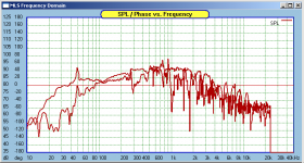
First I measured my normal 10" bass speakers, with graphs for both driver and port shown.
edit: Yes, I know I have a little mains noise creeping in with the new cables, but the setup is exactly the same for both boxes.
First I measured my normal 10" bass speakers, with graphs for both driver and port shown.
edit: Yes, I know I have a little mains noise creeping in with the new cables, but the setup is exactly the same for both boxes.
Attachments
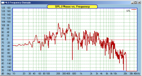
pinkmouse said:And now with the mic moved over to the TH. Nothing else has been changed at all.
Those look better, there´s something happening below 100 Hz.
Why the curve don´t look like the sim, I dont know.
Sorry I couldn´t help.
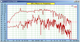
Indeed the curves do look better, but the problem still remains. Here's a (level shifted) comparison of the TH with the merged ported box response. If you knock out the 50Hz buzz, we're back to the TH FR peak shifted up by a factor of ten again. I really am confused.
Attachments
"'Dig' how deep with what HF corner? How small? I mean this driver has a ~322 Hz mass corner, so combined with a 66 Hz Fs its ~flat LF BW is fairly limited, but the upside is it sims 120 dB/2 pi space/~55 Hz - up/~113 W with just one in ~112.6 L net, which by my standards is tiny . As already noted, you can add inductance to smooth it somewhat.
GM"
Thanks GM!
Cheers
Johannes.
GM"
Thanks GM!
Cheers
Johannes.
pinkmouse said:Indeed the curves do look better, but the problem still remains. Here's a (level shifted) comparison of the TH with the merged ported box response. If you knock out the 50Hz buzz, we're back to the TH FR peak shifted up by a factor of ten again. I really am confused.
With no MLS measuring experience beyond watching others use it and seeing how often minute changes in the mic position can dramatically affect measured response combined with no 'hands on' TP experience, the only other obvious variables would be if the driver's specs are way off the published ones I used or there is a driver associated leak keeping from allowing pipe action.
GM
Circlomanen said:
Thanks GM!
You're welcome! I assume from your response that my alignment is the one you plan to build. If so, please report back with at least a basic performance review.
GM
Tentative suggestions
Now you have good resolution it is easier to try to analyse what is going on. I'm sure the factor of 10 is a red herring - but I'm offering the ramble below as food for discussion rather than an explanation.
Some differences between the model and reality that could be expected include:
i) variable damping of the pipe modes (>100 Hz): I don't think these modes could be expected to have the uniform, low damping that the model assumes (due to unmodelled loss at bends, flexing walls, etc.). So some of those big peaks in the model could end up smaller and broader, while others could stick up like the model predicts. Unfortunately I don't find this explanation all the convincing, as I'd have expected at least one of the lower-frequency modes (100 to 200 Hz) to have low damping, and stick out clearly - the match to the model is worse than I'd have thought.
ii) frequency of pipe modes: again details of the geometry that are not in the model will change these (I'd not be surprised at ~10% differences, but lack experience to be sure what to expect).
So perhaps those two peaks above 200 and below 500 Hz are just the least-damped pipe modes?
iii) room effects, down below 20 Hz the room gain could easily explain the flat response rather than the predicted high pass.
I'm watching your experience with great interest, as I'll be in the same position in 4~6 weeks with another TH.
Ken
pinkmouse said:Indeed the curves do look better, but the problem still remains. Here's a (level shifted) comparison of the TH with the merged ported box response. If you knock out the 50Hz buzz, we're back to the TH FR peak shifted up by a factor of ten again. I really am confused.
Now you have good resolution it is easier to try to analyse what is going on. I'm sure the factor of 10 is a red herring - but I'm offering the ramble below as food for discussion rather than an explanation.
Some differences between the model and reality that could be expected include:
i) variable damping of the pipe modes (>100 Hz): I don't think these modes could be expected to have the uniform, low damping that the model assumes (due to unmodelled loss at bends, flexing walls, etc.). So some of those big peaks in the model could end up smaller and broader, while others could stick up like the model predicts. Unfortunately I don't find this explanation all the convincing, as I'd have expected at least one of the lower-frequency modes (100 to 200 Hz) to have low damping, and stick out clearly - the match to the model is worse than I'd have thought.
ii) frequency of pipe modes: again details of the geometry that are not in the model will change these (I'd not be surprised at ~10% differences, but lack experience to be sure what to expect).
So perhaps those two peaks above 200 and below 500 Hz are just the least-damped pipe modes?
iii) room effects, down below 20 Hz the room gain could easily explain the flat response rather than the predicted high pass.
I'm watching your experience with great interest, as I'll be in the same position in 4~6 weeks with another TH.
Ken
- Home
- Loudspeakers
- Subwoofers
- Collaborative Tapped horn project