You'll need two pairs of output devices to support 45V rails. It's untested, but if you go this route you'll probably want to entertain a few changes.
I'm not aware of any P3A PCB clones that accommodate this. Do you plan to design your own boards?
- The output devices should have emitter resistors to allow for current sharing. 0R1 is probably fine for this.
- Driver collector resistors R11/R12 can be dropped from 220R to 100R to supply the additional current needed to drive two devices.
- The OPS resistors R13/R14 will need to have a higher power rating. They're spec'd at 3W to 5W with one pair. For 2 pairs and 8R loads, you'll want 5W at a minimum. If you plan on driving 4R loads, You'll want at least 10W for these, maybe larger.
I'm not aware of any P3A PCB clones that accommodate this. Do you plan to design your own boards?
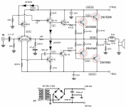
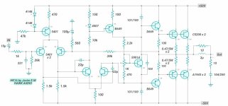
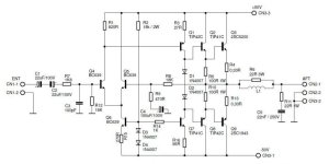
My idea is to use a single 5200 - 1943 output pair because I don't need that much power. I would like to know if the accompanying schematics are known and if they could work. (In all cases with a single pair 5200-1943). I would make the corresponding PCB. Thank you
Attachments

- Home
- Amplifiers
- Solid State
- Comparing P3A Schematics