I couldn't find any description of Cherry NDFL , but I found an amplifier circuit designed by the author here https://linearaudio.nl/sites/linearaudio.net/files/cherry ndfl amp.pdf
I add the rush added stage , biased at 3ma as described, add, devided my 3pf Miller into two and feedbacked as indicated. I let you conclude ,without comment, by your own .

Hayk
I add the rush added stage , biased at 3ma as described, add, devided my 3pf Miller into two and feedbacked as indicated. I let you conclude ,without comment, by your own .
Hayk
Attachments

Last edited:
I feel sorry you are out of this thread. And I thought Damir means , strong as iron in Turkish. You are always welcome back.
Please sim the LKA's design. If your sim can not replicate the loop gain as LKA, then your simulation is wrong. The loop gain is two pole, except you do not understand what pole is.
Please sim the LKA's design. If your sim can not replicate the loop gain as LKA, then your simulation is wrong. The loop gain is two pole, except you do not understand what pole is.
You can make as many poles you want in loop gain, but what is important here is the open loop character.
He breaks the feedback loop before the Cherry capacitor 100pf by this the phase response is wrong as it must include in the loop to act .
Last edited:
I see now the tric. The the poles are carried at the input stage not at VAS, LKA , you should have warned .I will study it mor carefully ,as I made a model that gave nearly the same .
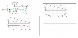
This is the approximate model of the amplifier. Unlike what explained to dadod , the 100pf capacitor is not a Cherry. Along the series 2.7k it shunts the input output of the power stage . When I measure the open loop response, I get similar behavior withe about 1.5khz first pole but minimum phase margin at lower frequencies and a second pole. The circuit not being easy to make precise estimation what is due to overall feedback what is internal, I measure the open loop character by the output impedance. There is the deception, the second order low pass function desapeared.

The curve shown is inverse of the measured voltage.
Hayk
The curve shown is inverse of the measured voltage.
Hayk
Attachments

dadod's OITPC

The 2.7pf has been split into two equal as instructed here OITPC - Output inclusive TPC (not TMC)
No comments.
Hayk
The 2.7pf has been split into two equal as instructed here OITPC - Output inclusive TPC (not TMC)
No comments.
Hayk
Attachments

Last edited:

The future 2 pole compensation
I started to design my own way of 2 pole. For me, a two pole is nothing but a second order low pass ,but degenerated to first order above a certain frequency. Second order means it is resonant with Q. Mathematically speaking a degenerated second order is 1/(s²+k₁s+w₁²) +k₂/(s+w₂). This function is simulated by LCR components

I tried a LCR network on the initial non compensated circuit , I could get a very good adjusted 46khz with 50° phase margin.

Now I will implement this transfer on the transimpedance VAS circuit using feedbacks .
Hayk
I started to design my own way of 2 pole. For me, a two pole is nothing but a second order low pass ,but degenerated to first order above a certain frequency. Second order means it is resonant with Q. Mathematically speaking a degenerated second order is 1/(s²+k₁s+w₁²) +k₂/(s+w₂). This function is simulated by LCR components
I tried a LCR network on the initial non compensated circuit , I could get a very good adjusted 46khz with 50° phase margin.
Now I will implement this transfer on the transimpedance VAS circuit using feedbacks .
Hayk
Attachments


The phase plots indicate active poles. Can single pole anything reverse trajectory of phase?
Yes, negative capacitance. When there is multiple poles involved it us possible to add a capacitor feedbacking positively ,it adds a negative pole , that is it makes the amplitude to continue decreasing while the phase shift decrease. This can be applied if the output stage is inverting type.
Hi, Hayk!
Feel free to visit our thread about the same thing vith some competition "who more".
Sorry, it's in russian, but here we use the same trannies, resistances and capacitances...
😉
????????? ????????? + ???????
Feel free to visit our thread about the same thing vith some competition "who more".
Sorry, it's in russian, but here we use the same trannies, resistances and capacitances...
😉
????????? ????????? + ???????
I made comparison between four compensation schemes TMIC,TMC,MIC,MC. Compensation capacitors values Ck1,Ck2 were preserved. THD20 follows the loop gain at 20kHz as expected.
Hi LKA, so let me start with making sure I get the acronyms:
TMIC: Transitional Miller Input Compensation
TMC: Transitional Miller Compensation (The one in Bob Cordell's book)
MIC: Miller inclusive compensation (The one that some call Cherry)
MC: Miller compensation
Questions:
- Do you have a good resource that describes TMIC?
- Given you tried TMC, did you try TPC (two pole compensation)?
I am interested to see how TMC, TPC and TMIC stack against each other.
Thanks!
I started to implement the transfer function. This is the first result. It is slightly less than 50° phase margin but 50khz.
C2R9 adjust the cut frequency ,R10 adjust the Q, C3 the dominant pole and R8 the phase advance at 20Mhz. I added C4 2pf on the load to represent the input capacitance of the output stage.
Attachments

Last edited:

OK guys, we have gone over if TMC is a two or one pole compensation before. This is the conclusion:
- From the perspective of the input stage and the overall open loop of the amplifier (AOL), TMC is single pole. It is essentially a Miller compensation (single pole) that at lower freq. is wrapped around the second stage and OPS, and a higher frequency is wrapped around the second stage only.
- From the perspective of the OPS, it is 2 pole. This is a lot more difficult to see intuitively. I'll post an intuitive explanation once I come up with one. In the meantime, attached is an analysis I hand-wrote some time ago.
Enjoy!
I looked carefully your calculation of TMS. First you consider the VAS as low impedance voltage amp , but it is high impedance 1M current amplifier. This is important because the cut frequency which will become the dominant single pole depends on C1 and the current gain. Second error is the calculation of the feedbacking network impedance . As assumed the C2 and R see the Vo. Then the impedance is 1/C1s +R//1/C2s that is
1/C1s +1/(1/R+C2s). You can see from this equation that at audio frequencies 68pf measures very high and 1/R is very high bringing the second term negligible . This makes it simply a first order low pass function. I simulated for you with R =1K and 1 ohm you see there is no any difference. If I bring the current gain to 1 the frequency is ten times higher.
Try to enjoy
Hayk
Attachments


Last edited:
I looked carefully your calculation of TMS. First you consider the VAS as low impedance voltage amp , but it is high impedance 1M current amplifier.
Hi Hayk, the ideal GM block has the following characteristics:
- Infinite input impedance
- Infinite output impedance
- Voltage in, current out.
- Voltage to current gain = GM
so your claim is wrong. Maybe you use different electronic symbols.
Also I have no idea what is TMS.
Second, the equations are correct and were verified in simulation. Try again.
These results have been published in the past in the forum, so results are not new. Search posts by Michael Kiwanuka. My value add was to show the equations.
Try harder.Try to enjoy.
Can you show me a stand alone working TMC? I simulated that of dadod it is Tzzz.
I have seen absurd gadgets but this exceeds everything.
This is the circuit of your calculation.

I am unable to understand how someone pretending of engineering minded doesn't see the resistor and the capacitor are paralleled.
Iam trying very hard to accept 1+1=11
I have seen absurd gadgets but this exceeds everything.
This is the circuit of your calculation.
I am unable to understand how someone pretending of engineering minded doesn't see the resistor and the capacitor are paralleled.
Iam trying very hard to accept 1+1=11
Attachments

Last edited:
In your description Gm is positive. That is on the contrary of a mosfet , it sources not drains current. Here what oscillator it becomes. Most VAS, use grounded emitters , why you didn't chose inverting current multiplier?
Attachments

Last edited:
Two brilliant engineers accusing each other of being wrong.
Knock it off you two.......... this benefits no one.
Knock it off you two.......... this benefits no one.
Two brilliant engineers accusing each other of being wrong.
Knock it off you two.......... this benefits no one.
It does, It shows the hoax created about this type compensation. Calculations, books, patents,a Joe Faller said so, etc.
In the biginning of the last century all scientists including Einstine , considered the outer space was filled with a substance they called it ,ether. All characteristic of this substance was known, the density , elasticity,specific heat ,etc. If it was to continue convincing others because himself convinced , where would we be now.
Last edited:
Two brilliant engineers accusing each other of being wrong.
Knock it off you two.......... this benefits no one.
Hey! I am being very polite here... all I said is that my analysis is right and not wrong as Hayk claims.
Next post (#41) shows the sim results to validate the analysis.
Last edited:
- Home
- Amplifiers
- Solid State
- Comparison Of 2 Pole Compensations