I have no sound coming out of an Elekit Tube Amplifier and have pulled out some diodes and resistors that returned wrong values from an initial run over with a multimeter. When I test with the component tester they fail but when I use the multimeter they appear ok. How can this be?
Specifically?
Component type, expected value, measured value with tester, measured value with DMM.
Post pics of the displayed readings from the tester.
You have to put the effort in if you expect a helpful reply.
Component type, expected value, measured value with tester, measured value with DMM.
Post pics of the displayed readings from the tester.
You have to put the effort in if you expect a helpful reply.
Component Tester = 'YD-CS Transistor Tester'
Multimeter = Kuman WH5000A
No sound coming out of an Elekit Tube Amplifier.
I tested a 12ohm Resistor on board and got a 6.1ohm reading from the Multimeter. After removal the Multimeter gave me the correct 12ohm reading but the Tester gave 'Unknown or damaged part'
I tested a Diode on board that read .507v with positive to anode and 2.124v with positive to cathode from the Multimeter. After removal the Multimeter correctly read .507v from the anode and OL from the cathode but the Tester gave 'Unknown or damaged part'.
Which instrument do I believe?
The Tester works well with unused components.
Components in circuit are often going to measure different (ie wrong) as they are in a circuit with other components.
The multimeter behaviour all sounds normal. Perhaps there's a fault with the component tester, or perhaps
it cannot measure low-valued resistors, and is checking leakage currents for diodes and being more fussy than
the multimeter for reverse-bias. Its perfectly possible for a diode to partially fail, showing much worse reverse
leakage but still basically working in a crude test.
I'd suspect the diode, be happy the resistor is OK, and probably trust both instruments (except the component tester
on very low resistances? Its probably assuming its a shorted out semiconductor).
Has the amplifier kit ever worked?
Is this a new build or one that has failed in service?
Does one channel or both have no sound?
Are you connecting the component to different numbered contacts of the tester as many contacts are common?
My tester measured a 3r3 resistor no trouble & I assume all testers are basically clones.
Is this a new build or one that has failed in service?
Does one channel or both have no sound?
Are you connecting the component to different numbered contacts of the tester as many contacts are common?
My tester measured a 3r3 resistor no trouble & I assume all testers are basically clones.
Maybe I´m an old fashioned greybeard (hey, I am 😉 ) but I trust a meter 1000 times over a generic cheap component tester any day of the week.
MAIN difference is that I interpret results and take conclusions.
And units displayed in multimeters are set in stone for almost 200 years now (Volt - Ohm - Ampere) , are taught in Physics Courses, their Math is also set in stone, no space for doubts or arguing.
(Except in DIYAudio cable or capacitor threads, that is, but that´s another problem 😉 )
While Component Tester follows what its designer "thinks" is right or wrong.
I have no clue what HE was thinking when he wrote the software.
Not dissing them, they have a place in a workbench, but if differing from what a multimeter shows ... not hard to guess who I trust 🙂
Are you using a DMM with a meter movement? Otherwise, both DMM & component tester rely on chips & software.
At the moment I suspect noob error. We just have to wait while (s)he drip feeds the facts.
At the moment I suspect noob error. We just have to wait while (s)he drip feeds the facts.
Have you done any active (i.e. powered) circuit measrements? I trust voltmeter (better yet oscilloscope, if available) probing and am reluctant to remove a component until I'm very suspicious it's the culprit. Can you post a schematic to aid discussion and troubleshooting?
Happy New Year!
Steve
Happy New Year!
Steve
Check your connections because intermittent or open circuit connections will give the 'Unknown or damaged part' screen. The most common reason a component tester fails to recognise a working component in my experience is poor connection to the tester (e.g. flux on the leads) or incorrect connection (e.g. two leads in same input in tester, or in my case one of the duplicate inputs of the tester that does not work).
Check conditions, not parts.no sound coming out
Is there 100 to 300 volts somewhere in there?
Some resistors going to ground will have voltage (cathode resistors). Some won't (grid resistors). You may not need to know "exact right" values to find something "wrong!"
I am a noob and a 'he' when I last looked. Amplifiers and speakers have been with me since listening to Apache by the Shadows on my sister's Bush record player in the early 60s and an owner of a Quad 33/303 and 44/405.2 since the 70s. In retirement, with my grey beard, I did Dada's upgrades to the 33/303 and 405.2 and more recently built IPL's S2TLK speakers. The 44 is broken and I am looking to fix it when this current problem is resolved. My knowledge of electronics is basic but I want to improve it partly for the fun but also to give dementia a run for it's money.
I built Elekit's TU-8200R tube amp last week and instantly became a tube convert. In triode mode the 4w output was wonderful (and loud) on my S2TLK speakers. Unfortunately I had got the speaker output socket colours mixed up and took it apart to correct them. The amp has three circuit boards inter-connected with multi pin connectors. I didn't connect the final main board pins and on power up got a hum in the left speaker and no music. I probably should have shut down straight away but messed around checking the input feed. After correcting the mistake complete silence from the speakers though the tubes were lit up and I got sound from the headphone out. I ran over the boards with a DMM and got dodgy readings from the two diodes D1 & D2 and the 12ohm resistors R19,R20,R21&R22 were reading 6.1ohms. I assumed that the diodes were more likely to be part of the problem and I have ordered replacements. I noticed that R23 was 12ohm and should be 1Kohm and have replaced this.
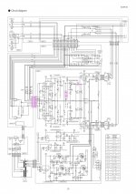
Taking the resistors and diodes out I checked them again with my DMM and a component tester and got differing results with the tester failing the diodes and resistors that the DMM was happy with. I double checked with a second DMM. I have included the circuit diagram and marked the connector and components in pink.
I will be grateful for any help. I coming round to doing a voltage check as the diagram and circuit board have all the relevant points and voltages marked.
What I am finding difficult is identifying correct replacements and ordering them. Is there a kit or advice about creating a personal store of components. It's very expensive ordering the odd few resistors or diodes. I have been using Mouser.
I built Elekit's TU-8200R tube amp last week and instantly became a tube convert. In triode mode the 4w output was wonderful (and loud) on my S2TLK speakers. Unfortunately I had got the speaker output socket colours mixed up and took it apart to correct them. The amp has three circuit boards inter-connected with multi pin connectors. I didn't connect the final main board pins and on power up got a hum in the left speaker and no music. I probably should have shut down straight away but messed around checking the input feed. After correcting the mistake complete silence from the speakers though the tubes were lit up and I got sound from the headphone out. I ran over the boards with a DMM and got dodgy readings from the two diodes D1 & D2 and the 12ohm resistors R19,R20,R21&R22 were reading 6.1ohms. I assumed that the diodes were more likely to be part of the problem and I have ordered replacements. I noticed that R23 was 12ohm and should be 1Kohm and have replaced this.
Taking the resistors and diodes out I checked them again with my DMM and a component tester and got differing results with the tester failing the diodes and resistors that the DMM was happy with. I double checked with a second DMM. I have included the circuit diagram and marked the connector and components in pink.
I will be grateful for any help. I coming round to doing a voltage check as the diagram and circuit board have all the relevant points and voltages marked.
What I am finding difficult is identifying correct replacements and ordering them. Is there a kit or advice about creating a personal store of components. It's very expensive ordering the odd few resistors or diodes. I have been using Mouser.
Attachments
Congrats on the IPL speakers.
My main speakers are IPL S3TL built several years ago. There won't be any more as Ivan has recently retired.
My main speakers are IPL S3TL built several years ago. There won't be any more as Ivan has recently retired.
Hi Chris,
Thanks for the schematic. It's very helpful.
You mention mesauring 6.1 ohm at R19 through R21, presumably measured in-circuit with power removed. This sounds about right--- R19 and R20 (and R21 and R21) in parallel make 6 ohms.
Would you be more specific about "dodgy" readings on D1 and D2? Note these components are shared with both channels. If one channel works properly, this bias source is probably not the problem in the other channel. Measuring operating voltages is probably the most efficient trouble-shooting technique. Remember that the working channel can be a guide to expected voltages in the defective channel. Be safe, one hand in lap while probing, etc---
It's possible the amp is working but signal path is open. Depending on your interest in this hobby, an oscilloscope can be invaluable.
Good luck!
If you were testing D1 and D2 in-circuit with a multi-meter's diode test function, these readings may be reasonable because of adjacent circuitry. If you observe about 1 to 1.2 V with circuit in operation, the diodes are likely behaving as intended.
- Home
- Design & Build
- Equipment & Tools
- Component Tester or Multimeter