good afternoon to all, i'm a DIYer and I would like to try something different..
and that's why I turned to you, and so I hope I can fix it and share the result with you..
I have spent the past few years using akabak and hornresp, enough for me, but now, I would like to build a 6.5 "midbass, complete with phase plug, but I would like to analyze the behavior of the wave through the phase plug.. and at the same time analyze the directivity and response of pase and frequency of a determined woofer (represented by t/s parameters)
i've tryed abec3 but it doesnt look exactly user friendly😕
I started from this project:
https://www.comsol.it/model/lumped-loudspeaker-driver-12295
i tryed to turn the model to 2D in 3D, but now I have some difficulty in defining the radiation of the acustics in the domains to determinate the vector for the acceleration of the woofer...
i'm not a engineer or student, but I would like to expand the possibilities of self-builders, to be able to simulate 360 ° a specific item.
For this I would like to provide to all a template or project,in which the input we have:
Driver t / s parameters
variable driver (my problem)
3d model enclosure whit sketch woofer, air domains and PLM
The COMSOL model file should be able to give away the results of sensitivity and Phase..after thath everyone adds what he wants,
But before it can go ahead I would need a little help me regarding the transformation of the t / s parameters in woofer acceleration function🙁🙁
in attached the simple 3d version of the comsol 2d Lumped Driver
Attachments

Driver/Horn Design Optimization Mission
Your first mission is to create a large format compression driver including the model for it. Use of an open frame driver as the basis for this effort, complicates the horn/driver design mission immensely.Unless you are going into the business, forget it. Open frame drivers suitable to drive a horn load through the second decade are hard to find or must be ordered as a custom build.
There are several mediun/large format compression drivers available, these include Community M4, JBL 2485J, JBL 2490H, JBL CMCD-81, JBL CMCD-61 and BMS 4599ND. Goto Unit and ALE make some remarkable units, with remarkable weights and prices as well.
See the work of Christensen to get some idea what you are up against in this first step.
https://www.comsol.com/paper/compression-driver-simulation-including-air-damping-in-phase-plug-10980
https://www.comsol.com/paper/download/83661/christensen_paper.pdf
For the first decade I would like to see PWK’s work ‘pumped’ through Comsol to include room geometry and dimension parameters.
For the third decade, it is remarkable how the use of an acoustic lens has been ignored by all.
Comsol may also be used for shape optimization of the horn body.
https://www.comsol.com/model/optimizing-the-shape-of-a-horn-4353
Regards,
WHG
Last edited:
good morning, thanks to the answer, to tell the truth I should design the trumpet for a medium horn powered by a b&c 6MBX44...to increase the response frequency of up to 3000Hz ... is essential a phase plug to decrease the volume of the compression chamber (and prevent various propagation delays) ... now you can imagine that no 2d program you can not simulate everything.. (unless it is not symmetrical along an axis, but a trumpet unless it conical it is not)..
in any case I wanted to create a template that you can use with any 3D model ...
in any case I wanted to create a template that you can use with any 3D model ...

Where did you get a comsol license?
But, i would start by introducing a plane wave to see what the geometry of the horn does to the wavefront. If you have a phaseplug attached to the horn it will reduce the throat area so drastically that if you use a properly matched phaseplug to the cone a plane wave will probably be a very good starting point. That way you can skip the ts parameters completely since they do not affect the transfer function of the horn itself anyways.
The quantities you are looking for, frequency response can then easily be obtained from standard operators as i have done myself in 3d comsol models.
Version 5.2a even features a built in directovity map!
Recommend ...
... you use Phase Plug geometry of the CMCD-61 [1] as a starting point.
PG Mission:
1) Reduce front cavity volume.
(you can tweak HF by setting resonance here but beware of clearance needed for [Xmax] when doing this)
2) Mitigate Cavity Standing Wave Modes
(three rings are sufficient to do this and the dust cap influences them as well)
3) Approximate a coherent wave front at plug exit.
(shoot for uniform volume velocity in the annuli as well)
[1] https://www.jblpro.com/ProductAttachments/CMCD_TechNote.pdf
anyway this the midhorn that i want to simulate first to build
... you use Phase Plug geometry of the CMCD-61 [1] as a starting point.
PG Mission:
1) Reduce front cavity volume.
(you can tweak HF by setting resonance here but beware of clearance needed for [Xmax] when doing this)
2) Mitigate Cavity Standing Wave Modes
(three rings are sufficient to do this and the dust cap influences them as well)
3) Approximate a coherent wave front at plug exit.
(shoot for uniform volume velocity in the annuli as well)
[1] https://www.jblpro.com/ProductAttachments/CMCD_TechNote.pdf
I was designing a large midbass horn using a 6.5" driver recently. I was trying to cover ~100Hz-800Hz. I simulated several phase plugs on plane wave tubes and found there was not much improvement over no phase plug - just a square entrance to the horn. I was getting a notch a bit above 2kHz that I could reduce or move around a bit with the plugs, but the results didn't seem worth it in the end. So just something to consider in your experimenting - a phase plug might not improve things enough to be worth the hassle.
6.5" isn't much more than a quarterwave at 800Hz, so there probably isn't much to fix phase-wise at that frequency.
Of course, but obviously I'd want it to be well behaved at least an octave above crossover. It is, only having problems around 2500Hz which is why I decided a phase plug wasn't worth it in my case.
Why this Compromise?
True, but for that range, I would be looking at a lot larger driver (VD) and then the roll of a phase plug might just be important. Without a decent compression ratio, efficiency goes down and the driver has to work harder to deliver the same output. If I am not getting a decade between c/o points then the frequency spectrum needs more division than that required by a well balanced, 3-way system.
Regards,
WHG
I was designing a large midbass horn using a 6.5" driver recently. I was trying to cover ~100Hz-800Hz. I simulated several phase plugs on plane wave tubes and found there was not much improvement over no phase plug - just a square entrance to the horn. I was getting a notch a bit above 2kHz that I could reduce or move around a bit with the plugs, but the results didn't seem worth it in the end. So just something to consider in your experimenting - a phase plug might not improve things enough to be worth the hassle.
True, but for that range, I would be looking at a lot larger driver (VD) and then the roll of a phase plug might just be important. Without a decent compression ratio, efficiency goes down and the driver has to work harder to deliver the same output. If I am not getting a decade between c/o points then the frequency spectrum needs more division than that required by a well balanced, 3-way system.
Regards,
WHG
Bill,
Of course you can do whatever you please but for my case, home audio and a very large horn where I want to explore sound quality benefits of a small diaphragm driver, a 6.5" has enough headroom for the output levels I want to play at (around 112dB/FS/1m/4pi from a single channel - room gain adds to that). Actually when you compare to the VD I use at 800Hz, a 6.5" with 3mm of excursion has headroom to spare at 100Hz assuming similarly good loading. I currently use a 4 way to control directivity better, so it doesn't bother me in the least to restrict bandwidth. It's actually a benefit as I have more room to play with crossovers to optimize system directivity, distortion / headroom and energy storage of the system.
Now I'll stop derailing the OP's thread.
Good morning everyone and thank you for valuable information
then I would distinguish between two elements
-to define the trumpet for the chosen woofer (300-3000hz range)
-simulate it in COMSOL
well i,ve one problem for point.
- how to definite a phase plug for the midbasses whit the concave dust cap, i suppose that the farest point of the dust cup (the center) the pressure generated there must be an advantage, so I dropped the idea of a like turbosound phase plug or this (http://www.centauriaudio.com.au/diy/plugs.html)...and I have chosen for simplicity to dimension a toroid ...but I do not know how to cover the cone without creating pressure problems ..
about comsol its corporate license i suppose, at work , I asked for help from a technician who uses it but was unable solve my question..in any case I'm working to resolve the function definition and luckily another user contacted me and we'll see if together we can define this holy radiated energy..
bye
?
If you are employing a big OS horn that gives you pattern control within the bandwidth of interest, then the LF loading you suppose will not be there. Of course conversely, use a traditional Salmon horn will sacrifice HF pattern control for LF loading. It is not a matter of my personal volition, but rather, it is simply the acoustics of the matter. WHG
Bill,
Of course you can do whatever you please but for my case, home audio and a very large horn where I want to explore sound quality benefits of a small diaphragm driver, a 6.5" has enough headroom for the output levels I want to play at (around 112dB/FS/1m/4pi from a single channel - room gain adds to that). Actually when you compare to the VD I use at 800Hz, a 6.5" with 3mm of excursion has headroom to spare at 100Hz assuming similarly good loading. I currently use a 4 way to control directivity better, so it doesn't bother me in the least to restrict bandwidth. It's actually a benefit as I have more room to play with crossovers to optimize system directivity, distortion / headroom and energy storage of the system.
Now I'll stop derailing the OP's thread.
If you are employing a big OS horn that gives you pattern control within the bandwidth of interest, then the LF loading you suppose will not be there. Of course conversely, use a traditional Salmon horn will sacrifice HF pattern control for LF loading. It is not a matter of my personal volition, but rather, it is simply the acoustics of the matter. WHG
Good morning everyone and thank you for valuable information
then I would distinguish between two elements
-to define the trumpet for the chosen woofer (300-3000hz range)
-simulate it in COMSOL
well i,ve one problem for point.
- how to definite a phase plug for the midbasses whit the concave dust cap, i suppose that the farest point of the dust cup (the center) the pressure generated there must be an advantage, so I dropped the idea of a like turbosound phase plug or this (http://www.centauriaudio.com.au/diy/plugs.html)...and I have chosen for simplicity to dimension a toroid ...but I do not know how to cover the cone without creating pressure problems ..
about comsol its corporate license i suppose, at work , I asked for help from a technician who uses it but was unable solve my question..in any case I'm working to resolve the function definition and luckily another user contacted me and we'll see if together we can define this holy radiated energy..
bye
The presence of a concave dust cap simplifies phase plug design. Again it should follow the diaphragm profile.
Use a compression ratio of about [Sd]:[St] = 4:1 to avoid "pressure problems". WHG
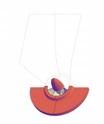
thanks a lot whgeiger....i've readed the jbl note, and here the compression ratio is indicated about 7/1..but they used a particular phase plug, anyway i've
I redesigned the phase plug, and I focused on a more traditional horn throat ad i've a ca 25cm2 of circular area free..
The woofer has a 3.5mm xmax, I thought that the distance between the phase plug and the cone can be 4mm, although the filtered woofer doesent reaches this excursion
I redesigned the phase plug, and I focused on a more traditional horn throat ad i've a ca 25cm2 of circular area free..
The woofer has a 3.5mm xmax, I thought that the distance between the phase plug and the cone can be 4mm, although the filtered woofer doesent reaches this excursion
Attachments

Notes
1) Plug/Diaphragm Clearance
You are not allowing for manufacturing tolerances and you are assuming that the driver will never be moderately overdriven beyond its [xmax]. Recommend 6mm min. clearance. Check driver [xmec] and use that as a guide.
[2] Phase Plug Geometry
Nix the center hole and use 2 or 3 annuli
[3] Phase Plug Design References
a) Smith & Murray
See Attached Files
ASAJ025-0305.pdf
AESP1384.pdf
b) Oclee-Brown (Important Work)
http://eprints.soton.ac.uk/348798/1.hasCoversheetVersion/Jack Oclee-Brown PhD Thesis.pdf
[4] Cone Driver Specifications for Horns
a) Small & Keel
See Attached Files
AESP1250.pdf
AESP1251.pdf
Regards,
WHG
thanks a lot whgeiger....i've readed the jbl note, and here the compression ratio is indicated about 7/1..but they used a particular phase plug, anyway i've
I redesigned the phase plug, and I focused on a more traditional horn throat ad i've a ca 25cm2 of circular area free..
The woofer has a 3.5mm xmax, I thought that the distance between the phase plug and the cone can be 4mm, although the filtered woofer doesent reaches this excursion
1) Plug/Diaphragm Clearance
You are not allowing for manufacturing tolerances and you are assuming that the driver will never be moderately overdriven beyond its [xmax]. Recommend 6mm min. clearance. Check driver [xmec] and use that as a guide.
[2] Phase Plug Geometry
Nix the center hole and use 2 or 3 annuli
[3] Phase Plug Design References
a) Smith & Murray
See Attached Files
ASAJ025-0305.pdf
AESP1384.pdf
b) Oclee-Brown (Important Work)
http://eprints.soton.ac.uk/348798/1.hasCoversheetVersion/Jack Oclee-Brown PhD Thesis.pdf
[4] Cone Driver Specifications for Horns
a) Small & Keel
See Attached Files
AESP1250.pdf
AESP1251.pdf
Regards,
WHG
Attachments
-
AESP1251-3.pdf644.2 KB · Views: 96
-
AESP1251-2.pdf821.4 KB · Views: 88
-
AESP1251-1.pdf611.8 KB · Views: 60
-
AESP1250-3.pdf403.6 KB · Views: 58
-
AESP1250-2.pdf432.3 KB · Views: 76
-
AESP1250-1.pdf531.2 KB · Views: 328
-
ASAJ025-0305.pdf225.5 KB · Views: 216
-
AESP1384-3.pdf894.3 KB · Views: 75
-
AESP1384-2.pdf842.8 KB · Views: 86
-
AESP1384-1.pdf727.4 KB · Views: 99

1) Plug/Diaphragm Clearance
You are not allowing for manufacturing tolerances and you are assuming that the driver will never be moderately overdriven beyond its [xmax]. Recommend 6mm min. clearance. Check driver [xmec] and use that as a guide.
[2] Phase Plug Geometry
Nix the center hole and use 2 or 3 annuli
[3] Phase Plug Design References
a) Smith & Murray
See Attached Files
ASAJ025-0305.pdf
AESP1384.pdf
b) Oclee-Brown (Important Work)
http://eprints.soton.ac.uk/348798/1.hasCoversheetVersion/Jack Oclee-Brown PhD Thesis.pdf
[4] Cone Driver Specifications for Horns
a) Small & Keel
See Attached Files
AESP1250.pdf
AESP1251.pdf
Regards,
WHG
Thanks for the links whgeiger, very good reading material!
Try This
Concept Drawing, dimensions only approximate, plug could be shorter as well. Horn section at mouth? Circular? Other?
Regards,
WHG
one step at a time ..but I need a 3D printer
anyway, i've used a mix of all documents proposed..the next step is procjet the horn and simulat all...
Concept Drawing, dimensions only approximate, plug could be shorter as well. Horn section at mouth? Circular? Other?
Regards,
WHG
Attachments

- Status
- Not open for further replies.
- Home
- Loudspeakers
- Multi-Way
- comsol 3d simulations