No, not really. I've bought a good dozen of the IF3602 dual version for€ 1K.Those IF3601 jfets are really nice! but at £20 each a bit pricey lol
That was a bad investment. The old data sheet promised much more,
and the update from 2 years ago got closer to reality, but still, let's say, optimistic.
You pay for the low noise with Cin in the nF range. For your mic capsule, that is
a short circuit.
IF has a selection service. I suppose, us Mouser customers get the outliers.
No, for the same Cin I can parallel dozens of CPH3910.
They are all individuals:
< >
Gerhard.
Last edited:
I saw the noise figure of the device thought very nice, but then saw the price and thought no. I didn't get as far as seeing the input cap value, a bit different to a little 2N3819, and yes a definite short circuit for the mic capsule !
Even the standard 2SK170 that a lot seem to use has a to big input capacitance value, it counteracts it's low noise level by attenuating the signal level. So a bit surprised the 2SK170 is used so much with condenser mics. I guess the noise floor level isn't so important for a lot of mic uses.
Even the standard 2SK170 that a lot seem to use has a to big input capacitance value, it counteracts it's low noise level by attenuating the signal level. So a bit surprised the 2SK170 is used so much with condenser mics. I guess the noise floor level isn't so important for a lot of mic uses.
The typical high-performance mic amplifier bootstraps the JFET to reduce its effective input capacitance.
Indeed, but that doesn't change the equivalent input noise.
Theoretically, for a JFET with a given fT, negligible gate leakage shot noise and negligible 1/f noise, there is a noise optimum when the JFET is made so large that its gate capacitance equals the capacitance of the signal source. I don't know if those assumptions are close enough to the truth, though.
Theoretically, for a JFET with a given fT, negligible gate leakage shot noise and negligible 1/f noise, there is a noise optimum when the JFET is made so large that its gate capacitance equals the capacitance of the signal source. I don't know if those assumptions are close enough to the truth, though.
H
HAYK
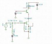
With my circuit that has 1Gohm to bias 60v the capsul and another 1G to ground the gate. I use common base bc550c for cascode.
I measure the total noise voltage for 10hz to 20khz bw.
The 2sk2394 with 18ma bias and the 2n5457 with 2.15ma both 12db gain, have similar noise.
I measure the total noise voltage for 10hz to 20khz bw.
The 2sk2394 with 18ma bias and the 2n5457 with 2.15ma both 12db gain, have similar noise.
Attachments


Good point about the second 1 Gohm resistor.
Pity you took the integrated noise rather than the density. A lot of that noise is subsonic or at frequencies that are barely audible. The interesting part is the increase between 1 kHz and 10 kHz, which is hardly visible like this. Is it input or output noise?
Pity you took the integrated noise rather than the density. A lot of that noise is subsonic or at frequencies that are barely audible. The interesting part is the increase between 1 kHz and 10 kHz, which is hardly visible like this. Is it input or output noise?
H
HAYK
At 20khz, it shows the rms value of the total noise at the output for 10hz to 20khz. The graph shows that most of the noise has occurred in the BW of 10hz to 100hz.
Which is hardly or not at all audible, that's just the point.
https://en.m.wikipedia.org/wiki/Equal-loudness_contour
https://en.m.wikipedia.org/wiki/Equal-loudness_contour
H
HAYK
A microphone can be used for acoustic measurement, this one will give lower dynamic range at low frequencies.
At 20khz, it shows the rms value of the total noise at the output for 10hz to 20khz. The graph shows that most of the noise has occurred in the BW of 10hz to 100hz.
Fortunately, in my application for the pre-amp I can filter out (HPF) most everything below the fundamental frequency of the average human voice (say everything below 150Hz), which will help cut the total noise level down. I do all the AGC, equalisation/spectrum shaping, noise reduction etc in software (DSP).
I presume you've done those noise graphs in TINA ? .. I don't yet know how to get LTSpice to graph total noise level.
Increasing the input resistor(s) from 1G to 10G reduces the final noise floor by a significant amount, but again it requires a digikey/mouser order.
Could also use thermal cooling of the pre-amp front end parts if we went the OCD route, just like we do with RF pre-amps and camera sensors for astro work etc, but that's not going to happen 😉
Could also use thermal cooling of the pre-amp front end parts if we went the OCD route, just like we do with RF pre-amps and camera sensors for astro work etc, but that's not going to happen 😉
H
HAYK
If I do remember, on ltspice noise graph, right click the noise graph title and you will get start and end frequencies to enter and you get the noise voltage.Fortunately, in my application for the pre-amp I can filter out (HPF) most everything below the fundamental frequency of the average human voice (say everything below 150Hz), which will help cut the total noise level down. I do all the AGC, equalisation/spectrum shaping, noise reduction etc in software (DSP).
I presume you've done those noise graphs in TINA ? .. I don't yet know how to get LTSpice to graph total noise level.
Most microphones of this type have switch to low cut.
The output must be differential.
EditI don't yet know how to get LTSpice to graph total noise level.
simulation - choose
noise analysis...
will give you noise density.
Absolute noise level is not available imho, you may multiply noise densitiy with sqrt(bandwidth) for a rough estimation.
One typical specimen, Bruel & Kjaer vintage #2619 capsule amp, bootstrapping the JFET and all biasing paths:The typical high-performance mic amplifier bootstraps the JFET to reduce its effective input capacitance.
I note that the bootstrap factor is slightly below unity to maintain stability. Interesting, the main JFET is partly biased by a NPN's leakage current and I think I've seen variants with JFET leakage biasing as well. Finally, the main JFET is the master in a CFP "precision" follower. A simple and effective circuit, and the head amps from Microtech Gefell from that era have very similar schematics, so this appears to be a proven concept.

DSP filtering (in software) is noiseless and totally adjustable, but I already have low and high cuts in the design that can be customised before the audio reaches the ADC input.If I do remember, on ltspice noise graph, right click the noise graph title and you will get start and end frequencies to enter and you get the noise voltage.
Most microphones of this type have switch to low cut.
The output must be differential.
Don't need differential as the ADC is right near the mic, no loooong runs of cabling, infact, the ADC might be included with the pre-amp along with a small CPU and radio chip to send the raw uncompressed samples to the main processing CPU wirelessly.
No typical XLR 48V system in use.
The capsule and gate biasing is done by two relatively small resistors, only 200 Mohm each. Apparently they were more worried about leakage than about noise.
V2 could be a snap-back device for ESD protection. Apparently a 2N4292 is specified to have a VCEO of only 15 V.
I saw a schematic the other day of a condenser mic that had no gate resistor clamp or anything, the mic condenser capsule went directly to the gate with no other components at all barring a small cap on the gate, just floating ..
Apparently they dare to rely on the gate leakage. At power-on, the gate is forward biased until the capsule is charged, so you don't get a long start-up time. I wonder how they physically constructed it; PCB connection with guard rings, in the air?
Biasing the other side of the capsule is a nice trick to ensure you don't need an extra noise-current-injecting resistor for that.
Biasing the other side of the capsule is a nice trick to ensure you don't need an extra noise-current-injecting resistor for that.
- Home
- Amplifiers
- Solid State
- Condenser mic jFET pre-amp design