For home recording purposes, I am hoping to implement the following 70.7 volt speaker system with attenuation. See Below. I am using a large crawl space to house the speaker cabinets and microphones. The source tube amplifiers (various 4 & 50 watt amps), mic preamps and the Digital Audio Workstation will be in another room over 70 feet away. I will be running 16 gauge speaker wire to the cabinet(s). Will the line matching audio transformers serve their purpose and will the tube amps maintain their stability when connected to this attenuating distribution system (i.e. not overheat, impedence, etc.)? I want to ensure my tube amps are not over stressed.
An externally hosted image should be here but it was not working when we last tested it.
An externally hosted image should be here but it was not working when we last tested it.
Just run a straight cable (16 Ga is somewhat thin but still acceptable) from head to speakers.
1 or 2 ohms (at most) in series with speakers will not be a problem and in fact may slightly improve sound.
Do not add transformers in the path, even less ones which can be switched to different taps.
You will be degrading sound more than adding 1 or 2 ohms in series, at worse you have the potential of killing your amp.
Just don't.
As a side note, if you think this is a way which will allow you to attenuate speaker out , DO NOT , you will kill your amp.
"Attenuation" in PA distributed sound works with constant voltage lines; the output of a guitar tube amp, even more if overdriven, is NOT.
THE IMPEDANCE MISMATCH WILL KILL YOUR AMP , capisce?
JMFahey, can you explain how the amp is going to fail? I could see losing some top end response with this arrangement for guitar, but not killing the amp.
No audio amp has constant voltage output. The 70.7 volt tap is merely another tap on the transformer allowing smaller wire (lower current) for distribution of speakers over a large area. Intercom systems wired similarly would not have worked, if I understand you correctly. See Bogen MO-100 for a typical PA amp of this type. I used one as a power amp for bass. We also drove synchronous motors with it in the lab from the 110V tap using a variable frequency sine wave. 🙂 The amplifier had no issues whatsoever.
The only difference here from an intercom system is the derivation of the 70.7 volt bus. In an intercom system, you'd have a number of speakers each with a matching transformer connected to the bus in parallel, or a number of attenuators each feeding a speaker group.
Last edited:
FWIW, 70.7 volts was picked to keep the peak voltage at 100 V for safety reasons. It later was dropped to 25 V to keep peak voltage below 40 V; this was driven by EU safety standards IIRC.
Typical distributed speakers PA type amps like the Bogen you mention are DESIGNED to be constant voltage output.JMFahey, can you explain how the amp is going to fail? I could see losing some top end response with this arrangement for guitar, but not killing the amp.
No audio amp has constant voltage output.
To achieve that, they have stiff "constant voltage"(duh) supplies; that does not mean that supplies are electronically regulated but designed with generous power transformers, thick low resistance windings, good filtering, to which they add using more output transistors than strictly needed for the rated power.
Just look at typical PA "commercial amps" schematics and you'll see.
To boot, all modern ones (modern meaning from the late 60'son, go figure) are SS, which by itself means constant voltage/low internal impedance output.
As we all know, SS amps have no trouble with no load, meaning infinite impedance.
Those using an output autotransformer to drive 70V lines, have to be careful with that transformer inductance which may produce dangerous flyback peaks, but that is tamed already at the designer's board in two ways:
a) those autotransformers are driven from a very low impedance generators (the SS amps themselves) which keep a tighter control on them than the Tube version, which I'll comment on later.
b) two reverse biased diodes are added, from amp output/autotransformer input to +V and -V rails, so any undue peak is clamped to +/- 0.7V above or below said rails ... no big deal 😉
All this means that a PA amp is perfectly happy and safe even if users attenuate music.
Suppose each room transformer in a large Hotel or Mall or office building has 1/2/5/10W taps.
Even if the switch is labelled "attenuation" (although "power" is more common and accurate) what it actually does is to vary the impedance reflected into the line so the speaker "pulls" less power from it (since it shows higher impedance than expected) and the impedance rise follows "attenuation" , so if all switches are set to "1W" instead of "10W", the amp will see 10X the nominal impedance ... no big deal because it's built to accept that.
So if the amplifier is , say, an 8 ohms output one (which is converted to 70V line with an autotransformer), when all speakers are set to 1W instead of 10W the amp will see reflected 80 ohms ... no big deal for an SS amp.
BUT, if our friend's TUBE amp, which is NOT a PA amp but a guitar one, is connected to an autotransformer to raise output to 70V , the speaker connected to a complementary one at the other end, and he decides he wants to attenuate the power he's listening in the recording room, and he lowers the switch setting to, say, 1/10th the power ... what he'll actually do is to multiply the impedance seen by his guitar amp by 10X ...... which will destroy it.
He might puncture the transformer insulation, arc inside a tube or simply arc and carbonize a socket ... pick your poison, they are all deadly 🙁
How, then can tube guitar amps be attenuated?
because attenuators are:
a) reasonably constant impedance, power is attenuated but amp always sees a reasonable , safe load.
b) they can dissipate the full power turning it into heat, they are basically resistive (although some add some reactance to simulate a speaker, they are still mainly resistive)
while a selectable power distribution transformer (as shown in the posted schematic) is NOT an attenuator but a simple variable ratio transformer, it does not dissipate power by itself (besides small losses) and is purely inductive , a guarantee of high undamped flyback peaks.
This is the very long winded explanation which was resumed in my first answer as: "avoid those transformers, connect head to speakers direct with plain cable".
Yes, I know that, not what's being discussed here.the 70.7 volt tap is merely another tap on the transformer allowing smaller wire (lower current) for distribution of speakers over a large area.
I didn't say that at all, but that including a switch selectable multitap transformer in the intended use was dangerous, hope I made myself clear by now.Intercom systems wired similarly would not have worked, if I understand you correctly.
The OP seemed to consider it a viable guitar amp attenuation system, which it's not.
Excellent amp.See Bogen MO-100 for a typical PA amp of this type.
Exactly, but the opposite of what's being discussed here: you used a robust PA amp to straight drive a Bass cabinet, I presume just using a regular cable and with no multitap transformer at the cabinet end; the OP shows a multitap transformer, at the other end of the line, hints at using it as attenuator, guitar amps are usually overdriven ... you did nothing of that.I used one as a power amp for bass. We also drove synchronous motors with it in the lab from the 110V tap using a variable frequency sine wave. 🙂 The amplifier had no issues whatsoever.
As of driving a motor, that robust amp showed how well built and overdesigned it was ... try that with a "gueetar" amp 😀
That's not the "only" difference by a country mile, please read above, don't want to repeat myself again over and over.The only difference here from an intercom system is the derivation of the 70.7 volt bus. In an intercom system, you'd have a number of speakers each with a matching transformer connected to the bus in parallel, or a number of attenuators each feeding a speaker group.
The original schematic shows an Atlas multitap transformer used as an "attenuator"
Simple Math says that in the -27dB position voltage ratio will be (using http://www.sengpielaudio.com/calculator-gainloss.htm): 22.4:1 so impedance ratio will be 500:1 😱
That poor 50W 8 ohm transformer will see a load of 8*500= 4000 ohms.
Not at the plates but at the speaker tap. 😱
What do you think will happen when johnnybegood plays a chord or even a single note? 🙁
I'd much prefer to send 50W through a plain cable and have 45 or 40W reach the speaker because of resistive losses.
Hope my worries with the original idea are clear by now 🙂
Thanks for the input. Initially I could only find autotransformers through an internet search. However, after doing an extensive search I found that Edcor manufactures single phase transformers for both amplifier output and speaker distribution.
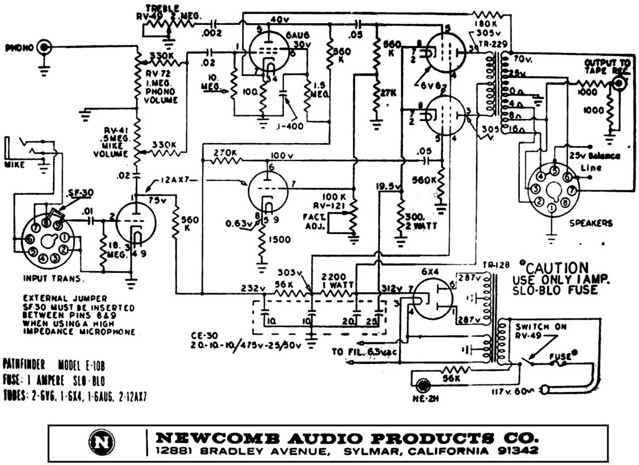
This whole idea came about because I found a schematic of the Newcomb Pathfinder PA tube amp that a couple of people have been converting to use as a guitar amp. The schematic for the Pathfinder below shows 70v and 25v output options along with the regular low impedance low voltage outputs.
See new schematic for this project. The secondary on the output distribution transformer and the primary on the speaker distribution transformer have their own isolated 70 volt windings. Can attenuation be achieved now with the Atlas AT-100 attenuator on the 70 volt independant line? As the voltage drops during attenuation the ratio in the speaker transformer remains a constant 8 ohms at the speaker tap.
No, the AT-AT100-RM "attenuator" WHICH IS NOT WHAT WE CALL AN ATTENUATOR IN THE GUITAR WORLD , DESPITE HAVING THE SAME NAME SO FORGET IT ONCE AND FOREVER is the game changer.
I don't care that you connect the speaker to a tap LABELLED 8 ohms and at the other end of the chain you have and Edcor and guitar OT properly connected bacause you are ADDING an impedance changing stage, the AT100 which can change it up to 500:1
What by the way does not happen in the Newcomb conversion.
EDIT:
Your tube amplifier will not like it, and that's an understatement.
I don't care that you connect the speaker to a tap LABELLED 8 ohms and at the other end of the chain you have and Edcor and guitar OT properly connected bacause you are ADDING an impedance changing stage, the AT100 which can change it up to 500:1
What by the way does not happen in the Newcomb conversion.
EDIT:
No.Can attenuation be achieved now with the Atlas AT-100 attenuator on the 70 volt independant line?
the impedance rises by the square of the attenuationAs the voltage drops during attenuation
INSIDE the EDCOR=WS=6=60 transformer, yes, but on the other side of the AT100, impedance changes with the square of the volts ratio, up to 500:1the ratio in the speaker transformer remains a constant 8 ohms at the speaker tap.
Your tube amplifier will not like it, and that's an understatement.
Last edited:
- Status
- Not open for further replies.
- Home
- Live Sound
- Instruments and Amps
- Connecting Guitar Tube Amp to External Line Match Audio Step Up Transformer