
Double check the MOSFET in your circuit. In post #1 you call for a 2N7002 which is an Nchannel enhancement mode MOSFET. Unlike discrete JFETs, discrete MOSFETs do not have interchangeable drain and source connections. And you've regrettably connected them backwards, with the source connected to a higher voltage than the drain. Any current which may flow is through the drain-to-substrate PN diode, not the MOSFET channel. It's a BJT current source in series with a PN diode. Probably not what you meant.
Last edited:


The way you test the impedance of a CCS in a sim is to drive it with a supply voltage with an AC component on it. Then you look at the CCS current, how much it varies as a result of the supply voltage modulation.
An ideal CCS would not vary in current.
The CCS impedance is delta-V/delta-I (Ohms'Law). For instance, if your supply AC component is 1V pk, and the CCS current variation is 1uA pk, the CCS impedance is 1V / 1uA = 1Megohm.
Jan
An ideal CCS would not vary in current.
The CCS impedance is delta-V/delta-I (Ohms'Law). For instance, if your supply AC component is 1V pk, and the CCS current variation is 1uA pk, the CCS impedance is 1V / 1uA = 1Megohm.
Jan
Last edited:

Some ideas in this thread and the previous one:
https://www.diyaudio.com/community/threads/improved-2w-current-sources-ii.197104/post-2720209
https://www.diyaudio.com/community/threads/improved-2w-current-sources-ii.197104/post-2720209
I think you'll discover that an even better result is achieved when the voltage drop across the emitter resistor (R22) is at least 200 * (kT/q), namely, 5.2 volts or greater. And you can get significant improvement at low frequencies ( < 10 Hz ) if you double regulate the reference voltage: Two zener diodes and two dropping resistors. Finally it can sometimes be helpful to plot the transistor's I-V curves and carefully check that they are constant current {not quasi-saturated} at Vce = 0.65 volts. You wouldn't want to operate a transistor at Vce = Vbe = 0.65 volts, if it isn't constant current there.Looks like the best result is achieved by using cascoded constant current source.
_
Attachments


Good fun!
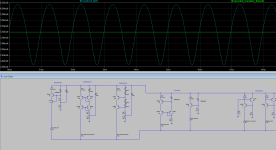
I have updated my sim to have two voltage sources, one is 20V DC, another is sine wave generator biased to 20V
and with amplitude of 10V (goes up to 30V and down to 10V)
I have threw together few designs and I see a great improvement going from usual feedback two BJT CCS to cascoded JFET.
It was fun trying to get resistor values to align sine waves on the graph on top of each other.... 😵🤣
Bunch of screenshots and sim file attached.
Attachments


Last edited:
If I understand correctly, CCS is essential in PSRR of the LTP. The better the regulation the better is the PSRR.
I wonder if cascoding LTP improves PSRR as well?
Regulation of one of my favorite CSS which is cascoded using dual SMD transistors is around 0.00018 mA of variation. Not too bad... Comparing to 0.22mA of usual two BJT in feedback. That is 1200x improvement. Another benefit is low voltage transistors can be used as their Vce basically add to each other by using cascode.
Last edited:
That's a lot of AC. Are you sure none of the CCS's run outof headroom?I have updated my sim to have two voltage sources, one is 20V DC, another is sine wave generator biased to 20V
and with amplitude of 10V (goes up to 30V and down to 10V)
You are trying to simulate the AC ripple on a supply so 1V AC is enough and will make sure the comparisons are more 'fairly'.
Jan

I suppose I could add one more diode drop to push things 0.65V ish?I think you'll discover that an even better result is achieved when the voltage drop across the emitter resistor (R22) is at least 200 * (kT/q), namely, 5.2 volts or greater. And you can get significant improvement at low frequencies ( < 10 Hz ) if you double regulate the reference voltage: Two zener diodes and two dropping resistors. Finally it can sometimes be helpful to plot the transistor's I-V curves and carefully check that they are constant current {not quasi-saturated} at Vce = 0.65 volts. You wouldn't want to operate a transistor at Vce = Vbe = 0.65 volts, if it isn't constant current there.
_
For those transistors that don't like operating at Vce=0.65
Will that move them to Vce=0.13V on the graph?
I'm still learning the basics here lol
I am attaching graph for 2n5401
Is that correct one?
Seems like 2n5401 is low Vce type of transistor.
Attachments

Last edited:
It depends, some JFETs are symmetric, some are not, some MOSFETs are symmetric, some aren't (the 4-terminal sort with the substrate pinned-out for instance, although I think they went the way of the dinosaur - MOSFETs in logic chips are symmetric). Power MOSFETs are very asymmetric always though as they are optimized for charge-injection into the channel from the source and out of it into the drain.Unlike discrete JFETs, discrete MOSFETs do not have interchangeable drain and source connections.


The ultimate might be to replace R5 with a CCS.
That should then extend the high impedance to higher frequencies.
It could be a quick check with an LTspice current source.
Jan
That should then extend the high impedance to higher frequencies.
It could be a quick check with an LTspice current source.
Jan
- Home
- Amplifiers
- Solid State
- Constant current source for LTP - need help with LTSpice simulation