If you're stuck with some wrong value preamp pots e.g. 250K log, can you convert them to 100K log just by adding resistors? So in that case:
- Do you just add a resistor between input and ground (each end of the pot) e.g. 250K//150K = 93K. Or any other way?
- How does it affect tracking?
- Do you just add a resistor between input and ground (each end of the pot) e.g. 250K//150K = 93K. Or any other way?
- How does it affect tracking?
Use it as is, without any modification.
100k or 250k is all the same ... if the following stage input capacitance is low.
Paralleling with resistor act as voltage divider (Rout of previous stage ->250K//150K), but it's almost nothing (for example 1..2k->93k divider), and only exact divider at low frequency.
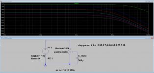
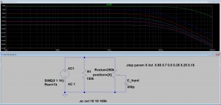
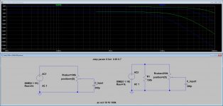
The real frequency dependent voltage divider is remains 250k -slider position- and 2nd tube stage capacitance (even few hundred pF).
Thanks Bela. I don't quite see what you mean by "voltage divider" though. If the track goes from 250K to 93K aren't you just converting a 250K log pot to a 93K log pot?
So..... original question, how would this affect tracking versus a real 100K log pot?
So..... original question, how would this affect tracking versus a real 100K log pot?
The Rout of previous stage and 93k act as a voltage divider, the output of preamplifier a few percent lesser, than the "not loaded" output voltage.
The 250k pot "sees" this voltage.
When you turning of the pot, the pot "upper" resistance and the "lower" resistance also operate as divider, but due to the power amp input capacitance act as a low pass filter.


p.s. it's a linear pot, but it's now unimportant.
The 250k pot "sees" this voltage.
When you turning of the pot, the pot "upper" resistance and the "lower" resistance also operate as divider, but due to the power amp input capacitance act as a low pass filter.


p.s. it's a linear pot, but it's now unimportant.
Last edited:
Well, yes, a volume control is a voltage divider, that's clear. But 100K is a standard value for the input of a preamp (rather than 250K) presumably because 100K in series with the input is better than 250K in series, which would be the case at very low volumes. Am I missing something?
Since this is for tubes, the 250k pot would be better for the LF response of the tube sources, including the phono stage,Well, yes, a volume control is a voltage divider, that's clear. But 100K is a standard value for the input of a preamp (rather than 250K) presumably because 100K in series with the input is better than 250K in series, which would be the case at very low volumes.
but worse for the tube line amp, because of the higher maximum Rout (62k instead of 25k, at -6dB), which reduces
the HF response. So pick your poison.
Lower value carbon pots will tend to track better than higher value pots.
Last edited:
You are missing that you never ever have 100k or 250k in series with later stage input.Well, yes, a volume control is a voltage divider, that's clear. But 100K is a standard value for the input of a preamp (rather than 250K) presumably because 100K in series with the input is better than 250K in series, which would be the case at very low volumes. Am I missing something?
Both pot sections : Hot to Wiper and Wiper to Ground are in parallel if signal source driving pot is low impedance , which we must assume since you don´t even mention it.
Do the Math: worst case (halfway rotation) you will have either 62.5k or 25k in series.
At low volumes it will be far lower.
PS: what is 6SN7 grid capacitance?
Thanks for the reply. Input is a DAC line level 2V. I get 140R on the output.You are missing that you never ever have 100k or 250k in series with later stage input.
Both pot sections : Hot to Wiper and Wiper to Ground are in parallel if signal source driving pot is low impedance , which we must assume since you don´t even mention it.
Do the Math: worst case (halfway rotation) you will have either 62.5k or 25k in series.
At low volumes it will be far lower.
PS: what is 6SN7 grid capacitance?
Input capacitance for the 6SN7 is around 2.2pf but could be between 1.7pf and 2.7pf.
Isn't the input capacitance of a 6SN7 common cathode stage subject to Miller effect?
I think the effective load capacitance presented to the output of the pot would be Cin = Cgk + Cgp*(A+1)
For 6SN7:
A = 16
Cgp = 4.0pF
Cgk = 3.0pF
3.0pF + 4.0pF(16+1) = 71pF
Add a couple of pF to account for strays.
I'd say the input C of a 6SN7 common cathode stage will be around 75pF.
With a 250k pot at -6dB attenuation, the Zout will be 62.5k ohms,
62.5k in series with 75pF in parallel makes F3 = 33,953 Hz (which is kind of low)
Using 75pF input capacitance, here are some examples of how taper and FR changes with different RG values before and after pot over 6dB steps from 0 to -30dB. For "150k R" R2=1G, R6=150k. For "150k Front" R2=150k, R6=150k. For no R, both R2 and R6=1G. "300k Each" is pictured.
Attachments
The upper is 100k (at 0.95 and 0.7 wiper value).Which is the 250K plot and which is the 280K//150K=93K plot?
The lower is 250k//150k.
- Home
- Amplifiers
- Tubes / Valves
- Converting a 250K preamp volume pot to 100K....


