Hi,
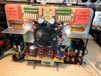
I am using Ohmite brown devils [200 series] for Cathode bypass and for reducing voltage on the driver valve power supply circuit. The amplifier is a 211 and the power consumed is about 3.5W on each of the cathodes and driver valve circuit uses a resistor that consumes about 9W to drop 300V.
I am able to push air through with some convection and some from low noise fans that move air around the underside of the amplifier near the resistors so they can dissipate some heat BUT they are both placed near some potential complimentary heat sinks (Copper plate 3mm thick and large aluminium plate 19mm thick). Clearly these resistors are designed to be in free space but I can't help but wonder if it would be advantageous to use a direct contact also to the plates to take some additional heat away.
Any more useful thoughts from experienced amplifier builders?
Thanks,
Rich
Is there any problem with using heat-sink mounted resistors in the first place?

Always follow the mfr spec. Those are for free air, so use the mfr brackets.
Clamping them to a hard surface may cause cracking from thermal expansion, especially if uneven.
Clamping them to a hard surface may cause cracking from thermal expansion, especially if uneven.
Id try and use the power resistors that are heat sink-able.
I bolt them to some aluminum or in Your case copper and they stay cool enough.
Plus they look way better than most cement resistors...
I bolt them to some aluminum or in Your case copper and they stay cool enough.
Plus they look way better than most cement resistors...
Thanks for all the feedback. I already have the heat sink type and they get the chokes and output transformers pretty hot, the aluminium plate gets up to 55 Deg C, and when I try to measure the underside resistor with a laser gauge it seems pretty cool, which is good, but all the heat gets taken through conduction upwards to the top of the plate where the chokes and transformers are bolted.
I have got a fan assembly, and I am going to blow some air past the resistors, but I am now in agreement taking a little also by conduction to the plates is a stupid idea.
I am hoping free air with some air movement will prevent the plate/heat sink getting too hot, and spread the heat out a bit instead of conducting it all into the plate. and then into the output transformers and chokes.