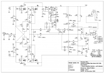
Hi All, I have rebuilt a Destiny Integrated with several new components. I've replaced the original HUF76639 MOSFETS with IRL2910 MOSFETS, which seem to be the best substitute. All seems to be working well. The idle voltage is stable around 21.5mV +/-.5mV every few minutes. I'm ecstatic it simply works after all the work I put into it. I've adjusted VR2 CW as little as possible for VR1 to adjust the idle voltage. I found that VR1 did take several turns before adjusting the idle voltage from .25 to 1 mV, and then rises exponentially WRT VR1. VR1 is around 30 ohms when idle voltage is at 21.5mV.
How important is fine tuning VR2? if I turn it CW this will increase the voltage across SR1 (LM336-5.0)(pins 4 and 8) passed 6 volts which is out of spec (4-6 volts) according to the data sheet. Right now SR1 (4-8) is at 5.93 volts. I am wondering if having adjusted VR2 out of factory settings will cause issues down the road with other components. Is adjusting VR2 important? If so, how should it be adjusted? Or are there other measurements I should make to verify the amp is working within design parameters? Any help is appreciated.
How important is fine tuning VR2? if I turn it CW this will increase the voltage across SR1 (LM336-5.0)(pins 4 and 8) passed 6 volts which is out of spec (4-6 volts) according to the data sheet. Right now SR1 (4-8) is at 5.93 volts. I am wondering if having adjusted VR2 out of factory settings will cause issues down the road with other components. Is adjusting VR2 important? If so, how should it be adjusted? Or are there other measurements I should make to verify the amp is working within design parameters? Any help is appreciated.
Attachments
Last edited:
VR2 adjusts the current for the voltage references and bias current plus temperature compensation to a nominal 5V, otherwise it could be in the range 4-6V as you say. It's guessing, but I would assume the expected reference voltage would first be adjusted to 5.0V to reduce problems in the spread of component parameters likely in production. So Q13 must require a stable and accurate reference for sensing temperature of the output stage and hence applying correct bias current compensation.
Last edited:
Turns out I just found the 5350SE schematic. I think the rail voltages are different but the schematics in the area of VR1 and VR2 are identical with the Destiny. The 5350SE lists VR1 also at 21.5mV, and VR2 at 600mV +/- 10mV. Is it safe to assume VR2 the same on the Destiny - 600mV +/- 10mV? If I bring down VR2 so the voltage across SR1 is 5, then the idle voltage cannot be adjusted. I think I might be at a compromise perhaps because I'm using the IRL2910 instead of the HUF76639. Thanks for your help.
Gregory
Gregory
Attachments
How different are the rail voltages? The Evolution 5350 MK2 is specified at +/- 40V with an output power of 120W/8R. There are original, 2nd editions, MK2 versions etc. of everything made by Creek so nothing is certain without all the service manuals. Even then, there may still be variations.
Evolution 5350 MK2 SE is rated 100W/8R so I would expect this to have a similar power supply but different transformer power rating since its 4R rating is 200W versus 160 for the Destiny. Otherwise, I would assume the settings to be the same unless someone comes up with exactly appropriate service details. for the model you have.
Evolution 5350 MK2 SE is rated 100W/8R so I would expect this to have a similar power supply but different transformer power rating since its 4R rating is 200W versus 160 for the Destiny. Otherwise, I would assume the settings to be the same unless someone comes up with exactly appropriate service details. for the model you have.
54V rails sound about right for 100W RMS. The 40V shown on Creek's 5350 MK2 schematic must be in error. So Id set it up to the same recommended settings but with the protection of a dim bulb tester (DBT). Never power anything with new construction or suspected faults without it or something electronic that also immediately throttles the current when it exceeds the expected normal low level after switch-on.
DMM probes get very slippery in sweating or shaky hands, which is what happens when you know you're in too deep. Take a break, look around for a clip lead or two. Even better, buy some cheap IC clips which if the larger size, about 50mm long, make great hook probes for occasional use. They're also available online in red/black meter lead pairs, fitted with safety banana plugs that simply plug into your DMM. Once clipped, no slip. You can also buy fancy, big Pomona model hook probes at absurdly expensive prices but unless you have a need to decorate your workspace with pro equipment, you'll soon be exceeding pro. service costs with your equipment purchases.
Probing solder joints with a blunt point is a sure way to slip and do damage too. I did a lot as a teenager, when all you could get were rounded probes but now you get sharp, hard points which are ideal. Use them or grind up any blunt hard metal ones you find.
Thats like butter fingers - the rounded probes! I learned on this amp, and luckily didn't destroy it. There was a small fire on one of the rectifiers, I bent the board to align the MOSFETs to the heat sinker presser causing a bad connection in a resistor which led to a whooshing sound in the left speaker and eventually fault protection mode. I've gone through 3 sets of MOSFETS, had to reconnect detached pads from overheating the board to desolder capacitors in the preamp section. My mistakes have been patched up luckily. Who knows for how long. This is my 3rd attempt at fixing it, and it works now except for the right channel dc offset, which I believe is measured across R112, 10mV, before its fed to the DC Servo circuit to be reduced at 3-6mV. I think I understand the sequence. Is that right? I don't know if the right dc offset is an issue, really. I have already ordered new electrolytic caps Nichicon PWs in efforts to improve the dc offset and wrap up the work. I found out about the capacitor plague that occurred around the time this amp was built. I have the clip leads and those have saved much time and stress. Yes late at night sticking probes in poor lighting. lol. I'll get a dim bulb tester. Thanks again for the help. I'll stick with the VR2 at 600mV.

Are you saying that Creek effectively suggested IRL2910 as a good replacement for the original HUF76639P3? That would be very useful to know, as HUF76639P3 is now obsolete and hard to find...Creek Audio responded to my email query and confirmed per design the voltage for VR2 (measured across JP3) is 600mV, even with the alternate MOSFET they’ve acknowledged is IRL2910.
")
Yes, Creek confirmed IRL2910 is an alternate to the HUF76639P3. Just responded to your email. I measured Vgs at just below 2Volts. The lower limit doesn't seem to be an issue.
Super. Many thanks for the help!
The newest edition of the service manual which includes values for VR2 can be found at
https://www.hifiengine.com/manual_library/creek/destiny-int.shtml
https://www.hifiengine.com/manual_library/creek/destiny-int.shtml
Hi Peter,
Congrats . I'm listening to my Destiny as I type. I still love how this amp sounds and hope to keep it for a decade or two longer with all the components I replaced. I am sure i replaced more than half of the amp. I installed Nichicon PWs for the 2200uF caps. And recently replaced the 6 wire input cabling with CAT8 24awg network cable which did improve channel separation but honestly can’t say I hear an improvement. Anyway, Glad to know there are more options for the output devices. I wonder how and if the lower RDS On value (~4mOhms) might changed the sound signature. Did you notice any change in the overall sound? I would have tried the IRL4030PFB if I knew about them a couple years ago when I replaced. I'm not sure if your amp has the same thermal issues caused by the 2k2 resistors in the Main Board as mine. If that's the case, one workaround is replacing the surface mount 2k2 power resistors- (R8(108), R9(109), R38(138), R39(139)) with through hole resistors. These 4 surface mount 2k2 resistors generate around 3 Watts in a rather small region and heat up nearby components to 60-70C+.
Best Regards,
Gregory
Congrats
. I'm listening to my Destiny as I type. I still love how this amp sounds and hope to keep it for a decade or two longer with all the components I replaced. I am sure i replaced more than half of the amp. I installed Nichicon PWs for the 2200uF caps. And recently replaced the 6 wire input cabling with CAT8 24awg network cable which did improve channel separation but honestly can’t say I hear an improvement. Anyway, Glad to know there are more options for the output devices. I wonder how and if the lower RDS On value (~4mOhms) might changed the sound signature. Did you notice any change in the overall sound? I would have tried the IRL4030PFB if I knew about them a couple years ago when I replaced. I'm not sure if your amp has the same thermal issues caused by the 2k2 resistors in the Main Board as mine. If that's the case, one workaround is replacing the surface mount 2k2 power resistors- (R8(108), R9(109), R38(138), R39(139)) with through hole resistors. These 4 surface mount 2k2 resistors generate around 3 Watts in a rather small region and heat up nearby components to 60-70C+.Best Regards,
Gregory
Last edited:
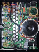
PS here's a photo of my amp with my modifications: Soldered most of the board to board connections after finding hum issues especially at JP1(101), 2k2 resistors moved above the board, replaced the LR Input to Volume cabling with CAT8, and bypassed preamp/amp switch.
Attachments
Last edited:
- Home
- Amplifiers
- Solid State
- Creek Audio Destiny: Help with adjusting VR2