
Thanks for the replies - but it is the hyrid I am intrigued by. It seems that he gets away with one 12AX7 + two MOSFets - that is the most minimalist approach I've seen and it would be interesting to see how that's actually done. So, I'll keep looking.
Were you able to find anything about the 7R?
this design has become one of the great secrets of the audio...
this design has become one of the great secrets of the audio...
To Edues.
No, not really. But I found some photos - and Stereophile's review of it. By looking at the pictures and doing a bit of guesswork I ended up with the attached schematic. I checked its performance with Stereophile's measurements and my version measures very close to those data Stereophile found.
There are, however, two differences: It seems that Glen Croft used a separate regulated bias supply for the output Mosfets. I use a traditional resistor network. Croft's version might be better in that the bias supply is completely independent of the main power supply, thus fluctuations caused by varying load on the main PSU are non-existent. Mine might be improved by adding electrolytic capacitors from the 15K drop-resistor to ground. This ought to stabilizes the biassupply somewhat. The other difference is the tubebased, regulated B+ supply. Croft uses this in some versions, but not all. However, even though the regulated B+ supply does nothing to the measured performance, it "mellows" the sound and makes it more musical.
Important note: As stated: I have never seen the schematic of the Croft Series 7, nor have I seen a version of it in real life. So the schematic I publish here is NOT pinched or copied. However, if I have violated somebody's copyright or intellectual rights please let me know and I shall apologize and remove the schematic at once. Moreover: Anybody who might build it does so at his/her own risk. I do NOT accept any liability whatsoever.
Attachments

¡Guau!
Gracias,
Podrías poner la captura de pantalla más grande para que se ajuste a todo el esquema.
Gracias,
Podrías poner la captura de pantalla más grande para que se ajuste a todo el esquema.
I will use K/J or ECX lateral type power pairs instead of IRFP vertical type pair , also I will use some quality MKC capacitors for additional filtering of voltage bias sources instead of electrolytics ,and maybe some more modern substitution type for IRF830 driver transistor , or ECC82 instead of ECC83 for input VAS stage ?
Attachments

Well nothing is wrong to use noval 12BH7 tube , basically the more linear triode tube for the input VAS stage the better overall performance will be since this hybrid AB-class amp works open loop, or GNFB free , IMHO for some DIY amp variant even octal 6SN7 tube is one very good choice ,
btw, overall THD spectrum performance for such simple hybrid AB-class amp is very similar to the best full tube SET A-class amps or is even way better .
btw, overall THD spectrum performance for such simple hybrid AB-class amp is very similar to the best full tube SET A-class amps or is even way better .
Only a few simulations of the operation of various variants of hybrid amplifier circuits, the simulations were made by an exceptional expert in audio technology Mr. Aleksandar Petrov from Belarus,
in all variants he used the better quality IRF710 instead of the IRF830 because it has much less parasitic capacitance.
in all variants he used the better quality IRF710 instead of the IRF830 because it has much less parasitic capacitance.
Attachments


Basically, the circuit topology should look similar to the one shown under this URLs:
https://www.edn.com/hybrid-vacuum-tube-solid-state-audio-power-amplifier/
simplehybrid-tube-amplifier-with-mosfet-output
reliable-tube-mosfet-hybrid-amp
the-hybrid-class-a-amplifier
Hyp End
https://audioxpress.com/article/a-hybrid-tube-mosfet-headphone-amplifier
https://digilander.libero.it/essentialaudio/hybrid_circuit.htm
http://krishu.de/steinmusic-hybrid/
https://web.archive.org/web/20010306051737/http://www.steinmusic.com/
Navigation:
https://www.stereophile.com/content/croft-acoustics-phono-integrated-integrated-amplifier
and power amplifier
P.S.: in the attached PDF catalog from Steinmusic you will find some advice to find the best choice for the tube of front end.
https://www.edn.com/hybrid-vacuum-tube-solid-state-audio-power-amplifier/
simplehybrid-tube-amplifier-with-mosfet-output
reliable-tube-mosfet-hybrid-amp
the-hybrid-class-a-amplifier
Hyp End
https://audioxpress.com/article/a-hybrid-tube-mosfet-headphone-amplifier
https://digilander.libero.it/essentialaudio/hybrid_circuit.htm
http://krishu.de/steinmusic-hybrid/
https://web.archive.org/web/20010306051737/http://www.steinmusic.com/
Navigation:
- Steinmusic-Artikel
- Stereo - Hybridendstufe (German magazine Klang&Ton; 3/93) and additional pad
- Verstärker
- Hybridendstufe
https://www.stereophile.com/content/croft-acoustics-phono-integrated-integrated-amplifier
and power amplifier
P.S.: in the attached PDF catalog from Steinmusic you will find some advice to find the best choice for the tube of front end.
Attachments

Last edited:
supplement to previous post:
Croft Valve Hybrid Amplifier Gallery from Series 7
https://audioflair.co.uk/category/croft/
Croft Valve Hybrid Amplifier Gallery from Series 7
https://audioflair.co.uk/category/croft/
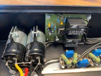
some images of a device from a friend in faulty condition
Attachments
-
 9e8a342d-bca1-4753-b08c-32495de1139d.jpg76.6 KB · Views: 82
 -
 914eea79-ff28-4793-bf56-8f0c8ff7fe3d.jpg95.8 KB · Views: 79
 -
 d2858e0d-4579-49f4-872b-c762be85c4ba.jpg125.7 KB · Views: 70
 -
 cb81ebb1-af28-495e-a1b8-5b23198809f7.jpg91 KB · Views: 76
 -
 659df378-908d-4d84-b03b-73fcecada4cb.jpg92 KB · Views: 76
 -
 c70b6a40-daad-422d-a94b-6b66bce0fb73.jpg68.4 KB · Views: 76
 -
 0bf9ccb4-7141-4574-ade2-4145fa60a3e6.jpg96.1 KB · Views: 75
 -
 22e300c7-d509-442b-9d22-c256c6442763.jpg76.5 KB · Views: 73
 -
 887d2df9-22b2-4be9-b0bc-8f54dcbac1d6.jpg112.6 KB · Views: 80
 -
 ee96d803-7c80-4312-871f-9d461057d190.jpg56.2 KB · Views: 71
 -
 b29306df-d491-4a83-9b4f-5a7aeec1d64f.jpg44 KB · Views: 67
 -
 b68c2be2-3e6d-4213-94f7-fd24c905c2d6.jpg69.5 KB · Views: 67
 -
 627308ed-dd78-4bae-80fd-952d645d646f.jpg78.6 KB · Views: 68
 -
 9c0a147b-7a7c-41cf-92cd-62e8a56d9328.jpg87.4 KB · Views: 89
the used MOSFETs according the image from attachment No 6 are those from the attached datasheet. check also this URLs:
https://www.exicon.info/why-use.php
https://www.exicon.info/products.php
Without the schematic I can't say, if it is power follower (buffer) configuration in the power output stage or not.
https://www.exicon.info/why-use.php
https://www.exicon.info/products.php
Without the schematic I can't say, if it is power follower (buffer) configuration in the power output stage or not.
Attachments
Last edited:
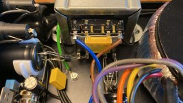
Yes, that's the output mosfets. I'm pretty sure it's just af plain source-follower. I was just wondering if you friend could read the number on the TO220 Mosfet on the ECC83 part?
It would not be hard to make a schematic from the pictures. It would be very similar to the schematic Hans Jørgen has shown.
It would not be hard to make a schematic from the pictures. It would be very similar to the schematic Hans Jørgen has shown.
I also can read the number on the Mosfets from the image - go to image No 6 - or mean you the TO220ISO Parts from image No 8 ?
I don't think, this parts are MOSFET's. Maybe this parts are voltage regulators used as CCS - like in the schematic from attached gif for the EL84.
I don't think, this parts are MOSFET's. Maybe this parts are voltage regulators used as CCS - like in the schematic from attached gif for the EL84.
Attachments

Last edited:
Yes, I mean the TO220 in image no.8. I'm 99.99% sure it's a mosfet.
ECC83 anode resistance is to high to drive the output mosfets directly. So Croft added this mosfet follower. The front en is exactly or very close to what is drawn in Klarskov's schematic. He just used different output stage using other mosfets. He uses the IRF830 as the source follower for the ECC83, but as far as I know it's just one he selected as an appropriate device and likely not the same as used in the original. It would just be interesting to know what Croft used in this position.
ECC83 anode resistance is to high to drive the output mosfets directly. So Croft added this mosfet follower. The front en is exactly or very close to what is drawn in Klarskov's schematic. He just used different output stage using other mosfets. He uses the IRF830 as the source follower for the ECC83, but as far as I know it's just one he selected as an appropriate device and likely not the same as used in the original. It would just be interesting to know what Croft used in this position.

- Home
- Amplifiers
- Tubes / Valves
- Croft Series 7