JensRasmussen said:I have looked at the datasheets, and indeed AD844 claims to be a current feedback opamp. However, at the same time the datasheet tells us that the AD844 can be used as a substitute for “normal opamps”. This for me is a contradiction, as the word current-feedback to me either means something about the external feedback network, or some sort of internal compensation circuit.
It is very simple (AD844) :
1) -input has input resistance of 50 Ohm even without FB,
2) open loop transresistance is 3 MOhm and FB resistor must be kept several orders lower in magnitude, also for the reason of neglecting Cfb,
3) Provided Rfb is kept low (500 Ohm - 2 kOhm) the bandwith does not depend much on (voltage) gain, i.e. GBW increases with increasing (voltage) gain,
4) input bias currents are quite high and unmatched,
5) the OA is not SR limited.
These are typical attributes of so called CFB OA and I consider the term CFB useful. I work on regular basis both with VFB and CFB opamps.
PMA,
Ok, I see your point, but it does not match the definition of current feedback I know, as the feedback signal have no relation to the outgoing current.
I guess we are back where we started; there are several definitions that share names, without describing the same kind of circuitry.
PJOTR,
I would probably call it series shunt…. Voltage feedback. Because there is no relation between outgoing current and feedback signal….
But again that’s up to the definition you use
What would you call it, and why?
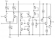
I hope it's ok I copied the schematic, so it's easier to compare to my drawing.
\Jens
Ok, I see your point, but it does not match the definition of current feedback I know, as the feedback signal have no relation to the outgoing current.
I guess we are back where we started; there are several definitions that share names, without describing the same kind of circuitry.
An externally hosted image should be here but it was not working when we last tested it.
An externally hosted image should be here but it was not working when we last tested it.
PJOTR,
I would probably call it series shunt…. Voltage feedback. Because there is no relation between outgoing current and feedback signal….
But again that’s up to the definition you use
What would you call it, and why?
I hope it's ok I copied the schematic, so it's easier to compare to my drawing.
\Jens
Jens,
I know, but I don't care. For me the 5 points that I have named are enough to distinguish between 2 kinds of OA topologies, regardless the "semantic" 😉 . This kind of argueing is not for me, as I am interested in properties of real circuits and their application 😉 .
BR,
Pavel
I know, but I don't care. For me the 5 points that I have named are enough to distinguish between 2 kinds of OA topologies, regardless the "semantic" 😉 . This kind of argueing is not for me, as I am interested in properties of real circuits and their application 😉 .
BR,
Pavel
LTP based input stage creates so called VFB opamp and emitter input singleton based input stage (and preferably symmetrical in polarity) creates so called CFB opamp - it is very simple.
Ouroboros said:And CFB architectures can work very well for audio.......
Sub-optimal...
JensRasmussen said:I would probably call it series shunt…. Voltage feedback........Jens
Correct....because the nominal feedback network's transfer function is a voltage. viz: (voltage/voltage).
Elementary....my dear Watson. 🙂
PMA said:LTP based input stage creates so called VFB opamp and emitter input singleton based input stage (and preferably symmetrical in polarity) creates so called CFB opamp - it is very simple.
Correct....in all respects.....Thanks Pavel!!!...

mikeks said:
Correct....in all respects.....Thanks Pavel!!!...
Very pleased, Michael 😉
mikeks said:
Correct....because the nominal feedback network's transfer function is a voltage. viz: (voltage/voltage).
Elementary....my dear Watson. 🙂
But since the inverting input has (or at least should have in
theory) a much lower input impedance than the resistance of
the gain resistor in the feedback network, the transfer function
isn't determined by the external feedback network alone. The
gain resistor sets the gain, but has little impact on the transient
behaviour for error voltages.
Hmm…
Not very satisfying. For AC we can consider the pos. branch and the neg. branch being in parallel. Now apply a delta-Y transformation to the emitter resistor and the feedback impedances…
Btw Jens, I favour the definition that when the (feedback) input of the amp senses current, the FB topology can be called CFB. I once read an (50 years) old description of a tube amp. The feedback from the output to the cathode of the input tube was called already CFB in those days.
<Edit>
Indeed Christer 😉
😉
Christer said:
But since the inverting input has (or at least should have in
theory) a much lower input impedance than the resistance of
the gain resistor in the feedback network, the transfer function
isn't determined by the external feedback network alone.
correct...the feedback network is deliberately selected to load down the first stage....i.e. reduce first stage gain as closed loop gain is reduced, (and conversely).....so that bandwidth appears constant....
the low feedbak network resistor values mean that the input stage runs in class-AB, which explains why you can have a much higher slew rate than the nominal quiescent current suggests....
mikeks said:
correct...the feedback network is deliberately selected to load down the first stage....i.e. reduce first stage gain as closed loop gain is reduced, (and conversely).....so that bandwidth appears constant....
the low feedbak network resistor values mean that the input stage runs in class-AB, which explains why you can have a much higher slew rate than the nominal quiescent current suggests....
There is nothing in what I said that implies loading down the
first stage. I just said that the input impedance (which is really
an output impedance) of the inverting input is/should be much
smaller than the feedback network impedance. There is no
implication that you must select the latter so low that you
are forced to run in class AB. Maybe the CFB op amps run
their input buffers in class AB, but I see no reason for a
discrete design to do so.
Christer said:
There is no implication that you must select the latter so low that you are forced to run in class AB. Maybe the CFB op amps run
their input buffers in class AB, but I see no reason for a
discrete design to do so.
True....
🙂
PMA said:LTP based input stage creates so called VFB opamp
not really. Most modern CFB opamps use a LTP input stage, 🙂.
the key is actually the 2nd stage: does it have a transimpedance amp or a voltage amp.
Pjotr said:Ok, here is a classic one:
http://www.bonavolta.ch/hobby/en/audio/hir20.htm
Now what would you call it? CFB or VFB?
VFB. The input voltage is connected to the base of the second stage via one Vbe offset of the input transistor, the feedback voltage is connected to the emitter of the second stage via the feedback network. The resultant driving voltage Vbe is the difference between input voltage and feedback voltage. More than that, the feedback network is a voltage source (< 10 ohms internal impedance) driving a 10 times higher input network (> 100 ohms).
Next time, ask me a hard one.😀
Jan Didden
janneman said:
VFB. The input voltage is connected to the base of the second stage via one Vbe offset of the input transistor, the feedback voltage is connected to the emitter of the second stage via the feedback network. The resultant driving voltage Vbe is the difference between input voltage and feedback voltage. More than that, the feedback network is a voltage source (< 10 ohms internal impedance) driving a 10 times higher input network (> 100 ohms).
Next time, ask me a hard one.😀
Jan Didden
Many discrete designs that seem intended as CFB amps have
to high negative-input impedance wrt. the feedback network
to be really considered CFB amps. Maybe they aren't intended
to be CFB amps after all? Yet, I think the impedance is also too low
to think of them as VFB amps. They actually land somewhere in
a greyzone inbetween. However, If we changed values so
the negative-input impedance were much lower than 10 Ohms,
and maybe also increased the impedance of the feedback
network, then it would be a different case, do you agree?
millwood said:
not really. Most modern CFB opamps use a LTP input stage, 🙂.
the key is actually the 2nd stage: does it have a transimpedance amp or a voltage amp.
Not at all. By CFB, the op amp manufacturers mean an amp
where the input stage is a unity gain buffer connected s.t.
the buffer input is the op amp positive input and the buffer
output is the op amp negative input and the output voltage
is proportional to the current flowing in the buffer output.
www.intersil.com/data/an/an9420.pdf
focus.ti.com/lit/an/slva051/slva051.pdf
focus.ti.com/lit/an/sloa021a/sloa021a.pdf
I would think they know what they mean themselves, at least. 🙂

Christer said:
Not at all. By CFB, the op amp manufacturers mean an amp
where the input stage is a unity gain buffer.....
Well...if i buffered a simple LTP input stage that wouldn't make it a so-called CFB would it??
- Status
- Not open for further replies.
- Home
- Amplifiers
- Solid State
- Current feedback - Voltage feedback, how do I see the difference?