Again the time base needs to be opened up.Pin 6 at 12 volts. It's 2 lines but they are so close you can't see in picView attachment 1160956
Pin 6 at 12 volts. It's 2 lines but they are so close you can't see in picView attachment 1160956
This looks to be rightPin 3 stays the same at 14 volts and this is pin 6 at 14View attachment 1160957
My oscilloscope doesn't show numbers for voltages. I need a better one. Testing with multimeter pin 3 shows nothing even at 14 volts. Should that zener diode have that voltage drop on zd1?
What are you using for solder work? Do you have a tip for working on SMD?
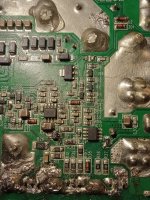
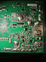
Not to be critical but looking at this board its hard to tell if there are any solder bridges, unsoldered pins or cold solder joints. Even a thin strand of solder or lifted pins can cause poor performance at a minimum.
Alcohol and a stiff brush is your friend. Clean up the PCB and you may want to redo solder around mosfets,Q5 and D2.
How hot are the mosfets getting when powered up?
Checked the good one and it has the same voltage drop. About to clean up the soldering job. The first time I put a 2045. In it looked far better. When I replaced it I was afraid to heat it up. No heat on fets. And above 14 volts it plays.
The ZD1 is a 3.1 volt zener, so it looks right.My oscilloscope doesn't show numbers for voltages. I need a better one. Testing with multimeter pin 3 shows nothing even at 14 volts. Should that zener diode have that voltage drop on zd1?
Correction: I meant Pin 4 IC16
Checked the good one and it has the same voltage drop. About to clean up the soldering job. The first time I put a 2045. In it looked far better. When I replaced it I was afraid to heat it up. No heat on fets. And above 14 volts it plays.
Okay so that amp appears to be good, other than less than 14 volt input. Go ahead and clean PCB and post another Pic. Not sure why it requires 14 volts to work, but we should be able to figure this out!
Okay so that amp appears to be good, other than less than 14 volt input. Go ahead and clean PCB and post another Pic. Not sure why it requires 14 volts to work, but we should be able to figure this out!
The first time I put the 2045 down I used the hot air station. I can't get it flat on the board with the iron
Clean the pads with desoldering wick. Add a small amount of solder to one pad. Place the 2045 and solder the leg on the pad that has solder. Push it down and then solder the other pads. I have a hot air station and never use it for SMD components.
I broke the chip. Gotta order some more. Can't see the markings on the first one that I pulled. And thanks again for the replies
If using desoldering braid, additional flux helps. Try searching ebay for:
Kester 186 951 reflow flux needle bottle xbox
You can often find both sold in one auction.
I prefer using acetone and a toothbrush (not one made of clear plastic, they melt) or cotton swabs for cleanup but use what works for you.
Kester 186 951 reflow flux needle bottle xbox
You can often find both sold in one auction.
I prefer using acetone and a toothbrush (not one made of clear plastic, they melt) or cotton swabs for cleanup but use what works for you.
Put the new 2045 in. Then the the fets started to warm up when powered on. So I thought they were bad. When i pulled the fets the amp powers on and drive looks as it should. When i got the new fets and installed them now it draws excessive current clips power supply and the fets heat up. R95 a 100 k resistor is reading like a cap. I replaced it still doing the same thing. I have no idea how to track down what's causing it. Thanks for any help


- Home
- General Interest
- Car Audio
- CXA1200.1 drive

