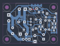
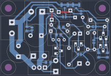
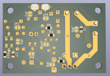
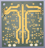
That's a good lookin design. Resistors and does are similar position in mine.
General question:
For power amplifiers, I've been routing small signal ground back to power supply ground bus separately.
I use the denoiser on preamps, phonograph preamps etc and have a separate signal ground going right to the last main smoothing cap...
Anyone have a reason not to do this (i.e. put all grounds through 1 wire from the supply)?
Thus, you use this point as a star ground. I am sure it works, but the smoothing cap environment is highly polluted by spikes of ripple current, and if you get something wrong, it will inject tiny differential voltages of ripple between the different grounds (through magnetic induction and parasitic resistances inside the pad itself).I use the denoiser on preamps, phonograph preamps etc and have a separate signal ground going right to the last main smoothing cap...
I would personally chose a quieter zone for a star ground, but if it works for you, why not?
Yes I use star ground arrangements as outlined by AndrewT years ago. (A copper bus bar close to the filter capacitor, noisiest grounds input nearest the capacitor, signal grounds furthest away).Thus, you use this point as a star ground. I am sure it works, but the smoothing cap environment is highly polluted by spikes of ripple current, and if you get something wrong, it will inject tiny differential voltages of ripple between the different grounds (through magnetic induction and parasitic resistances inside the pad itself).
I would personally chose a quieter zone for a star ground, but if it works for you, why not?
I will experiment with joining signal grounds at the preamp board.
Perhaps the chassis ground should remain near the filter cap?.
P.S. I tried denoiser on some diy and commercial phono preamps and highly recommend it. Never heard records sound so good.
Unless there is a good, objective reason, I don't think so: you want all the grounds to be as equipotential as possiblePerhaps the chassis ground should remain near the filter cap?.
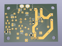
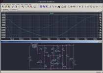
I didn't check your pinouts but the general layout is ok, should have good performance.Hi Trileru,
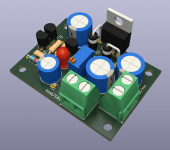
I have what I hope is the final version of the layout, based on the advice that you and the other here have so kindly given.
I've really enjoyed this as an intellectual exercise and have learned a lot about laying out a PCB from a schematic.
Having a power supply, the next step is to learn to lay out an op amp line level analogue circuit, probably a preamp or a active crossover.
I would be grateful if you wouldn't mind casting your eye over the PCB below as a sanity check to make sure I haven't connected something up incorrectly. I've tried to keep the loop areas small and take feedback from the right place as per your advice.
")
Managed to build an ADC and now I can take better measurements.
If we remove the protection resistor (10R-47R) we can push the performance even further with the help of the CCS.
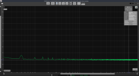
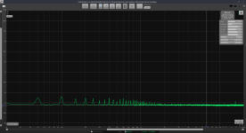
Best performance I could muster from the pcb, and measure was around 152dB of PSRR and the noisefloor at around the 444pV/sqrtHz level, or around 68nV total (20Hz-20kHz). I attached the measurement photos.
For this performance I used the ZTXx81 pair and set the CCS current to 20mA.
Input ripple was at around 0-1dBV with 200uF filtering capacitance (after the bridge), with 150R load at 12.2Vout, for around 100mAout total.
LNA's own noisefloor is at around 392pV/sqrtHz level or a total of 56nV (20Hz-20kHz).
ADC's virtual noisefloor with LNA's 60dB added comes at around the 39pV/sqrtHz level.
I used a Panasonic FC 100uF/63V as output capacitor (EEUFC1J101L).
LNA is battery powered in a metal case. PCB was powered with rectified AC for PSRR measurements and battery for noise measurements.
If you want to build the most performant version with CCS loaded dienoiser with the ZTX pair then you should add around 15-25nH in series with that output capacitor. For some reason adding ZTX951 to the mix requires that inductor for stability. This is valid for both ZTX851/ZTX951 and also MPSA06/ZTX951 combinations. I didn't need it for the other configurations.
I have no idea if the CCS loaded denoiser is stable without the compensation network. I had 33nF/1R in all my measurements and didn't need to adjust it. All measured combinations should be stable in the conditions I mentioned.
The LM317 regulator itself was a random one I grabbed from the parts bin. More exactly a ST LM317 marked "LM317T".
I didn't check the more performant LM317N from TI, but I don't think it will make much difference at this level.
I did several LM338 measurements and they're almost identical with the CCS versions.
If you want to build any of the boards (I'll post them in the next post) and you don't want the CCS circuit but like the LED as a power on indicator then just omit the CCS transistor and close a SMD jumper on the back.
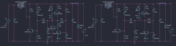
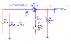
I attached the schematic I used for these measurements, the measurements themselves as screenshots in the measurements.zip file, and the LTSpice sim file with the circuits I measured with the values used in measurements. PSRR measurements have "_PSRR" text appended to the end of the filename.
You can get the LM317 spice model I used from here:
https://www.ti.com/product/LM317-N#design-tools-simulationFor a practical application I wouldn't bother with the ZTX pair. BC3x7 pair or MPSAx6 work great.
Each version is interesting, for example the CCS loaded denoiser (with ZTX851 I think) achieves a close PSRR to the normal dienoiser version.
If we remove the protection resistor (10R-47R) we can push the performance even further with the help of the CCS.
Best performance I could muster from the pcb, and measure was around 152dB of PSRR and the noisefloor at around the 444pV/sqrtHz level, or around 68nV total (20Hz-20kHz). I attached the measurement photos.
For this performance I used the ZTXx81 pair and set the CCS current to 20mA.
Input ripple was at around 0-1dBV with 200uF filtering capacitance (after the bridge), with 150R load at 12.2Vout, for around 100mAout total.
LNA's own noisefloor is at around 392pV/sqrtHz level or a total of 56nV (20Hz-20kHz).
ADC's virtual noisefloor with LNA's 60dB added comes at around the 39pV/sqrtHz level.
I used a Panasonic FC 100uF/63V as output capacitor (EEUFC1J101L).
LNA is battery powered in a metal case. PCB was powered with rectified AC for PSRR measurements and battery for noise measurements.
If you want to build the most performant version with CCS loaded dienoiser with the ZTX pair then you should add around 15-25nH in series with that output capacitor. For some reason adding ZTX951 to the mix requires that inductor for stability. This is valid for both ZTX851/ZTX951 and also MPSA06/ZTX951 combinations. I didn't need it for the other configurations.
I have no idea if the CCS loaded denoiser is stable without the compensation network. I had 33nF/1R in all my measurements and didn't need to adjust it. All measured combinations should be stable in the conditions I mentioned.
The LM317 regulator itself was a random one I grabbed from the parts bin. More exactly a ST LM317 marked "LM317T".
I didn't check the more performant LM317N from TI, but I don't think it will make much difference at this level.
I did several LM338 measurements and they're almost identical with the CCS versions.
If you want to build any of the boards (I'll post them in the next post) and you don't want the CCS circuit but like the LED as a power on indicator then just omit the CCS transistor and close a SMD jumper on the back.
I attached the schematic I used for these measurements, the measurements themselves as screenshots in the measurements.zip file, and the LTSpice sim file with the circuits I measured with the values used in measurements. PSRR measurements have "_PSRR" text appended to the end of the filename.
You can get the LM317 spice model I used from here:
https://www.ti.com/product/LM317-N#design-tools-simulationFor a practical application I wouldn't bother with the ZTX pair. BC3x7 pair or MPSAx6 work great.
Each version is interesting, for example the CCS loaded denoiser (with ZTX851 I think) achieves a close PSRR to the normal dienoiser version.
Attachments

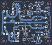
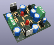
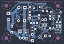
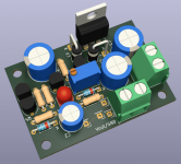
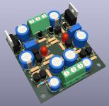
I made new pcb versions to include the CCS option + different extra jumpers to allow for all versions of the circuit.
There are 3 pcbs, single LM317, single LM337 and dual LM3x7.
I dropped the AC rectifying part of the circuit. I don't think it's a good idea to have AC so close to the low noise output. AC rectification should happen further away, maybe even in another case.
This way the dual board got even smaller. Single supply board is about 47mm x 35mm and dual is 61mm x 53mm. They should be good for max Iout of both LM3x7.
The single positive pcb can be used with LM338. All board designs have power traces exposed so you can fill them up with solder, to lower their resistance. This way you should be able to use LM338 to full Iout.
All the measurements in the previous post were done on the single positive pcb, the version I attached in this post has just a few extra jumpers and output capacitor series inductor footprint.
I put smd jumpers to short the protection resistors. This way you can decide if you want to use them or not.
There's jumpers for all modes, simple denoiser, dienoiser, or CCS loaded denoiser or CCS loaded dienoiser.
BJT footprints are for BC3x7. MPSA and other's might require you install them rotated. Check the datasheets and pinouts.
As usual these designs are diy-able, single layer. The single supply has only one topside pass, if you use gerbers then that's made by the pcb fab house. If you diy it then you need to install a small wire.
I attached the Kicad project files, each version has schematic pdf and diy pcb pdf, and gerbers zip files.
There's a 0805 footprint in series with the output capacitor. There's also a smd jumper next to it. If you use the correct ESR/ESL for the output cap then close this smd jumper. If you need to create the correct ESL or ESR then populate the 0805 footprint and leave that jumper open.
For example, CCS loaded dienoiser with ZTX pair requires the extra ESL. You either install a Panasonic FR 470uF/25V (EEUFR1E471L) and add around 150mOhm resistor on the 0805 footprint, either say a Panasonic FC 100uF/63V (EEUFC1J101L) which has the correct ESR and a series inductor like this. When choosing the inductor take into account its resistance. I'd go for a max of 50mOhms.
Attachments
-
 Screenshot_20220215_133418.png11.8 KB · Views: 220
 -
 Screenshot_20220215_133325.png19.6 KB · Views: 239
 -
 Screenshot_20220215_133650.png118.3 KB · Views: 233
 -
 Screenshot_20220215_133901.png123.9 KB · Views: 249
 -
 Screenshot_20220215_134330.png144.6 KB · Views: 235
 -
 Screenshot_20220215_134721.png156.6 KB · Views: 234
 -
kicad_projects.zip778.1 KB · Views: 157
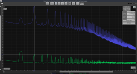
Finished measuring noise and PSRR for LM337. I used a ST LM337 marked "LM337SP"
This time I only measured the CCS loaded version for denoiser and dienoiser, using only MPSA and ZTX pairs.
The same as with LM317, when using a ZTX transistor for the dienoiser one you have to add a small series inductor with the output capacitor (there's a 0805 footprint on all pcbs) else it won't be stable.
I couldn't get it stable with ZTX851+MPSA56. I would personally avoid ZTX in both spots, and seems that lowest noise is achieved with ZTX851+MPSA56 for LM317 and ZTX951+MPSA06 for LM337.
The difference is not so great between 10mA and 20mA through the denoising circuit. I'd stick with 100R or so, seems like a good value.
Max PSRR was around 138dB and noisefloor sat at around 579pV/sqrtHz with LNA noise, and around 425pV/sqrtHz just for the regulator, with ZTX951+MPSA06.
edit: compensation values were 47nF+3.3R. It seems to need that 3.3R. With 22nF +3.3R some combinations would be on the verge. 47nF+3.3R worked with all the measured combinations.
output capacitor was that Panasonic FR 470uF/25V.
Attachments
Last edited:
Thanks for your efforts and contributions. For the nonoiser, I had to use a peculiar compensation scheme: a ferrite bead in the emitter of the main transistor. It might be an option worth exploring for your ultra-high performance variations.
A series inductance in the output cap might solve the problems, but I don't like this kind of solution very much: it dumbs down the very high frequency performance where only passives can do something useful.
A series inductance in the output cap might solve the problems, but I don't like this kind of solution very much: it dumbs down the very high frequency performance where only passives can do something useful.
Glad I could help!
I will try and add the ferrite bead as there's a high amount of gain. Simulation doesn't show any phase differences at higher frequencies which would be a good sign.
The pcb differences are small for the extra parts, I might be able to add everything on the same size pcb.
This might get the noisefloor closer to the discrete version (around 230pV/sqrtHz level).
You omitted the ESL of C2 in your analysis. Plug in and run an impedance plot out to 200MHz and look at the group delay.
A small inductance (as suggested) in the emitter of Q1 tames the issue unless someone has a 5 Watt 2 Meter handheld transceiver nearby.
A small inductance (as suggested) in the emitter of Q1 tames the issue unless someone has a 5 Watt 2 Meter handheld transceiver nearby.
So the NoNoiser works fine, I just finished measuring it.
I installed the ferrite bead on both ZTX851 and MPSA06. Compensation network was 33n/1R.
Seemed stable, didn't test without compensation network.
One thing is for sure, the CCS loaded dienoised NoNoiser is extremely slow start. We're talking minutes. Has a high swing, for 12Vout it goes to 14.5V on first swing.
0V-12V - 53 seconds
0V-14.4V - 1 minute 46 seconds
0V-14.4V and down to 12V again - 3 minutes. Goes to 11.4V or something on lowest swing.
CCS loaded nonoiser is faster:
0V-12V - 11 seconds
0V-14.5V - 27 seconds
0V-14.5V and down to 12V again - 1 minute.
I made these measurements with ZTX pair installed. With MPSAx6 the first swing seemed lower at 13.9V.
After startup you have to wait it out for 5 minutes or so (for measurements).
PSRR is crazy high, +150dB for CCS loaded NoNoiser and +160dB for CCS loaded dienoiser NoNoiser. I even got +170dB of PSRR depending on the DUT orientation my desk. I'm not sure my setup is reliable past 165dB.
Not much difference between the BJTs in this configuration. Very low noise and very high PSRR.
Out of all I personally like the CCS loaded NoNoiser the best.
I will post tomorrow the pcb I used for the measurements, and I will also make the LM337 version and also a dual version.
Not much difference between 10mA and 20mA. I'd stay with 100R for 10mA. I will do some more measurements when I get the chance, curious about lowest CCS current until performance starts dropping.
Attached a LTSpice sim file with the circuits I measured.
edit: for these measurements I used TI's LM317N, marked LM317T. Figured I'd put the best one I have for this board.
output cap was Panasonic FC 100uF/63V (EEUFC1J101L). didn't use the series inductor with it, it was stable without it in any configuration.
Attachments
Last edited:
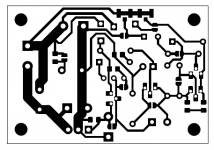
I finished the PCB designs for NoNoiser: single LM317 / single LM337 / dual LM3x7.
The singles got a bit longer at 51mm x 35mm.
The dual got a bit shorter at 57mm x 53mm.
There's jumpers for all denoiser circuit configurations including switching back to the classical two-resistor LM3x7 implementation.
I attached the Kicad projects along with PDFs for schematics, diy pcb and gerbers.
BJT pinouts are for BC3x7 pair. If you use other BJT mind the pinouts.
Previous measurements were made with the LM317 PCB I attached in this post. I didn't test the dual version so you make that at your own risk.
Attachments
-
 Screenshot_20220222_182140.png13.7 KB · Views: 216
 -
 Screenshot_20220222_182201.png9.8 KB · Views: 172
 -
 Screenshot_20220222_182116.png189.5 KB · Views: 187
 -
 Screenshot_20220222_174351.png120 KB · Views: 191
 -
 Screenshot_20220222_182238.png30.6 KB · Views: 178
 -
 Screenshot_20220222_182502.png16.9 KB · Views: 162
 -
 Screenshot_20220222_182443.png231.7 KB · Views: 193
 -
 Screenshot_20220222_173308.png155.9 KB · Views: 206
 -
pcb.zip841.8 KB · Views: 177
- Home
- Amplifiers
- Power Supplies
- D-Noizator: a magic active noise canceller to retrofit & upgrade any 317-based V.Reg.