Today I got this LM317 compact kit ad that could be easily integrated with a Denoizator or Dienoiser:
lm317 dc-dc 1.5a 1.2-37v adjustable power supply board dc converter buck step down module adjustable linear voltage regulator Sale - Banggood.com
lm317 dc-dc 1.5a 1.2-37v adjustable power supply board dc converter buck step down module adjustable linear voltage regulator Sale - Banggood.com
Which circuit is the canonical solution for the LM317?
I have some space left over on a proto board, but layout
must happen $(NOW). fab will be started today.
cheers, Gerhard
I have some space left over on a proto board, but layout
must happen $(NOW). fab will be started today.
cheers, Gerhard

... but it will take some time until I can test it.
Questions:
1) What program did you use?
2) Why traces are so thin? It seems to me you can easily make them 4 times wider, making them more soldering resistant and lower their resistance.
1.) Altium Designer
2.) This is just a test circuit without the intent to run large currents.
It can be used with the Altium snippet feature as a building block
for larger projects and then needs some massage anyway.
Just SMD layout default parameters.
2.) This is just a test circuit without the intent to run large currents.
It can be used with the Altium snippet feature as a building block
for larger projects and then needs some massage anyway.
Just SMD layout default parameters.
Those regulators have NO adjustment pin---only In, Ground, Out. There's NO place to inject the feedback signal.....?????Does anyone have an LTSpice model for 7XXX fixed voltages to sim Diego's Dienoisator for them?
Last edited:
See post 409/410 on page #41
Those regulators have NO adjustment pin---only In, Ground, Out. There's NO place to inject the feedback signal.....?????
Hmmmm...that's interesting; I had not seen that post---thanks for pointing it out. Has anyone actually BUILT and tested that circuit?See post 409/410 on page #41
I don't think so, but I am going to make a quick breadboard sanity check: no detailed measurements, but a basic, functional test. This should be enough to validate the concept.
Tested OK.
I take the opportunity to rectify one or two mistakes:
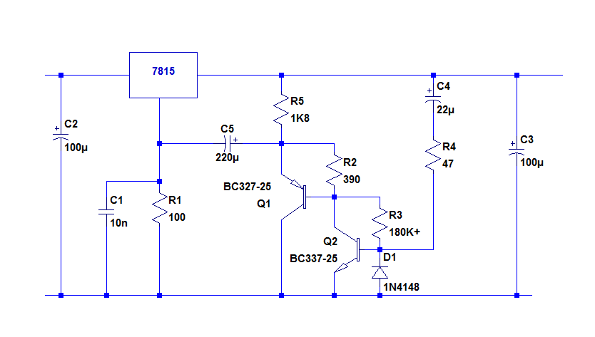
C5 needs to be reversed
R3 should be returned to the collector of Q2 to increase the Vce
R3 could be larger than 180K for the same reason
A compensation cap is required, as for other versions; a few nF is sufficient. 10nF is safe.
I take the opportunity to rectify one or two mistakes:
C5 needs to be reversed
R3 should be returned to the collector of Q2 to increase the Vce
R3 could be larger than 180K for the same reason
A compensation cap is required, as for other versions; a few nF is sufficient. 10nF is safe.
Attachments

Tested OK.
I take the opportunity to rectify one or two mistakes:

C5 needs to be reversed
R3 should be returned to the collector of Q2 to increase the Vce
R3 could be larger than 180K for the same reason
A compensation cap is required, as for other versions; a few nF is sufficient. 10nF is safe.
Thx for the great thread I am also asking for a group buy and some test result?
What about sound quality?
Could it be a great upgrade for my cheep volume with lm317/337 feeding PGA2310?
Thanks again
Thx for the great thread I am also asking for a group buy and some test result?
What about sound quality?
Could it be a great upgrade for my cheep volume with lm317/337 feeding PGA2310?
Thanks again
Hi Kimschips
I designed a dual rail board using lm317/337.
Post 518 page 52.
There are some gerber files that can be used to order pcbs from a PCB house like JLCpcb.
There is also a mouser BOM.
I can verify that the board works but we don't yet have noise figures. I'm waiting on Carlmart to do some noise measurements on one of my boards.
Tested OK.
I take the opportunity to rectify one or two mistakes:
C5 needs to be reversed
R3 should be returned to the collector of Q2 to increase the Vce
R3 could be larger than 180K for the same reason
A compensation cap is required, as for other versions; a few nF is sufficient. 10nF is safe.
Thanks Elvee for testing it and correcting the polarity of C5.
Have you tried R2 at 820 ohms, since that would be the recommended value for Vout = 15 V?. That would involve testing with the connection of R3 in the original schematic position and with the value at 330K, although, perhaps, it will reduce VCE (Q2) to near saturation values.
Possibly need to be implemented with a single transistor, similar to the denoiser (with less performance).
Regards
Last edited:
The sound quality will very much depend on the context: for example, a circuit using only good opamps will probably see no improvement, but many discrete circuits are very sensitive to the supply quality.What about sound quality?
Could it be a great upgrade for my cheep volume with lm317/337 feeding PGA2310?
Thanks again
I have no idea about the PGA2310, and the datasheet does not give a PSRR spec
No, I don't, but it is probably available on the Yahoo LTspice groupElvee,
Do you have an LTSpice model for the 7815?
As I said, I just made a functional test and no measurements, but resistors values could (and should) be suited to the supply voltage.Thanks Elvee for testing it and correcting the polarity of C5.
Have you tried R2 at 820 ohms, since that would be the recommended value for Vout = 15 V?. That would involve testing with the connection of R3 in the original schematic position and with the value at 330K, although, perhaps, it will reduce VCE (Q2) to near saturation values.
Possibly need to be implemented with a single transistor, similar to the denoiser (with less performance).
Regards
It would work with a single transistor, but the 100 ohm would shunt much of the gain away, and I think 2 transistors are preferable
- Home
- Amplifiers
- Power Supplies
- D-Noizator: a magic active noise canceller to retrofit & upgrade any 317-based VReg