Hi All,
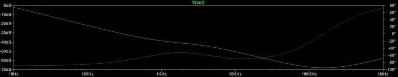
OK thanks for the tip - I used the AC analysis in LTSpice which was a new one for me. Results are in: see two frequency traces attached, one with just 2x 10mF capacitors (ESR and ESL added) and the other with the addition of a 2 microHenry inductor connecting the capacitors (with 12 mR series resistance). No bypass/parallel resistance.
As expected there is no difference below 1.5 kHz, but the attenuation in the range 10-100 kHz is quite significant. There is no sign of a gain peak at f0 as predicted. Seems good value for 80cm of bent copper (air core).
Attachments

Last edited:
I am not convinced that you need to filter these frequencies - much better to avoid generating them in the first case by careful design of the rectifier circuit. However, if you want a filter then you need to use appropriate component values: larger inductor and smaller capacitor!
At present I have no snubbers in my PS. Not seen the output on a scope yet. I already have my caps in place and they are staying. I need to make the best of the rest.
You need to think about the effect of a coil carrying charging pulses. This will spray an AC magnetic field around. Most people think about using twisted pair to connect capacitors (as AndrewT suggests) in order to minimise magnetic induction; you seem to want to maximise it!
I didn't think about this. Fair point. Is it better to have a simple direct connection between caps (no filter) or to install the filter? Surely depends if noise is observed.
I just assumed (in line with previous posts) that a filter could do no harm and might help.
How is the twisted pair constructed? Can you post a reference? Never heard of this. I'm interested.
Simulation results posted on another thread:
http://www.diyaudio.com/forums/power-supplies/305589-psud-usage-questions.html#post5027432
Thanks - popchops.
Last edited:
Won't the inductor choke the charging pulses ( which have a lot of higher freqs ) and increase your ripple?
The inductor would reshape the charging pulses, acting as an energy buffer to smoothe the change in current.
The inductor would reshape the charging pulses, acting as an energy buffer to smoothe the change in current.
By filtering out the higher freqs. It stops some of the energy reaching the cap. The amount of energy stored might not make up for that. It would
Be interesting to sim to see at what size an inductor starts to increase the ripple
I didn't realize the thread jumped; or that you asked SPICE. But anyway....
> 2x 10mF caps on each rail. ......inductor of about 1.5uH on each rail
You can rough-solve this with a stick in the dirt. (A calculator helps keep track of the decimal point.)
Being rough, I round "1.5uH" to 2uH.
freq --- 2uH ------ 10,000uFd
120Hz -- 0.0015r -- 0.14r
1KHz --- 0.012r --- 0.017r
5KHz --- 0.06r ---- 0.003r
By inspection, there will be a resonance just above 1KHz. (1.5uH and 10KuFd give 1,300Hz.)
If the resistance of the coil is greater than about 0.015 Ohms, the Q will be less than unity (low ring).
Let us "pretend" the caps have zero ESR. Real ESR will reduce Q.
DigiKey, 1.5uH, 2A-6A, thru-hole, finds 11 items with 0.008 to 0.047 Ohms.
The 38 cent part with 6,000 in stock is 0.020r, so will have Q=0.8 or so.
49 cents 4K in stock is 0.047r, Q like 0.3, no-ring for practical purpose.
10,000uFd 63V caps seem to have 0.015 to 0.050r ESR. So just one L-C will have 0.024 to 0.100 total resistance. Relative to 0.015r reactance, Q will be 0.6 to 0.15, all pretty mild.
So Q will not be a problem. But is it really attenuating the highs?
The DCRs add to the reactance (we'll blink-off the phase shift). And assume say 0.030r DCR in either coil or cap. So the real impedances are like:
freq --- 2uH ------ 10,000uFd
120Hz -- 0.03r ---- 0.14r
1KHz --- 0.042r --- 0.05r
5KHz --- 0.09r ---- 0.03r
20KHz -- 0.36r ---- 0.03r
So small attenuation at 1KHz and not even 10dB attenuation at 5KHz, 20dB at 20KHz.
Maybe it matters. Seems small to me. For $2 the experiment may be worth trying.
the sawtooth waveform you see on the smoothing cap tells you there is a fundamental at the charging frequency. This is either 100Hz or 120Hz (North America).
Riding on that fundamental are other harmonics. The sharper the points of the saw tooth the higher the frequencies (and proportions) of the harmonics.
If you pass the output from the first smoothing capacitor via TWO wires/traces to a second stage of smoothing you can compare the sawtooth waveform on the two capacitors.
When the impedance of the TWO wire connection is very low you will find the two sawtooth waveforms are virtually identical, both in height (Vpp ripple) and in shape (same quantity/proportion of harmonics relative to fundamental).
Now replace the two wire connection with one wire and a resistor for the other.
The resistor creates an RC filter with the second capacitor.
This will reduce the Vpp of the ripple. It will also reduce the harmonics content. Compare the sawtooth shape. You will see that the tips of the sawtooth are more rounded. This rounded shape tells you the proportion of high harmonic frequencies has been reduced. The filter is selective, it reduces the low harmonic a little and reduces the higher harmonics much more.
Now replace the resistor with a decent sized air core inductor with a resistance equal to the resistor in the previous experiment.
Compare the shape of the sawtooth. Compare the Vripple.
The Vripple will be almost the same because the resistance of the inductor is the same. This is the attenuation of the filter at the fundamental frequency. (you can use the F-3dB formula to predict at what frequency you startto get significant attenuation from the RC filter).
The sawtooth is starting to look like a sinewave that is skewed. Much of the high frequncies have been attenuated very significantly and the lower harmonics are reduced slightly. The clue is in the amount of rounding compared to the sharp points of the original.
I have found that 20T around an AA battery does little more than using an 0r1 resistor. (In fact I could see no difference).
But using 150Turns around a 22mm plastic pipe gives a very rounded (nearly sinewave) sawtooth.
Last edited:
Hi Andrew,
What's the downside? Why is inductance in the power supply so objectionable? Is the benefit of noise reduction outweighed by EM radiation from the coil? I will experiment with an off-the-shelf snubber across the secondary terminals. Better to avoid generating noise at source. I think everyone can see that. Thanks.
What's the downside? Why is inductance in the power supply so objectionable? Is the benefit of noise reduction outweighed by EM radiation from the coil? I will experiment with an off-the-shelf snubber across the secondary terminals. Better to avoid generating noise at source. I think everyone can see that. Thanks.
popchops, the harmonic magnitudes of the current passing through the diodes will drop off rapidly from the fundamental (2x mains f). Are you happy with the level of fundamental harmonic ripply voltage that exists at the first capacitor terminals, or have some target for the second cqpacitor?
Would the fundamental ripple voltage cause some performance degradation of your amplifier (assuming that is your use for the power supply), or are you unsure about amplifier performance?
If it is an amplifier, then are using one power supply for two amplifiers (stereo)?
Are you using two separate power transformer secondary windings and rectifying/filtering them independently so that you can use a "quiet end" star point for the pos and neg supply grounds?
Its always good to know what the real aim is.
rC maximimises the voltage delivered to the amplifier.
rCRC maximises the ripple attenuation and increases the Vdrop from rectifier to amplifier.
rC(L+R)C can maximise the voltage delivered to the amplifier if the R is kept small. And can attenuate the high harmonics if the L is made large.
The final C in ALL of the above is the main supply of current. The combination of this final C and the HF +MF supply rail decoupling supply ALL the current that flows to the speaker and to any correction circuits that draw transients.
Hi trobbins. I haven't yet seen the PS output on a scope. I can do this at work in the lab - but I don't have any quantitative targets. I have not built an amp before and may never do it again. (yeah right...)popchops, the harmonic magnitudes of the current passing through the diodes will drop off rapidly from the fundamental (2x mains f). Are you happy with the level of fundamental harmonic ripply voltage that exists at the first capacitor terminals, or have some target for the second cqpacitor?
The amplifier is suitable for an unregulated power supply with decent PSRR. Obviously, less ripple is better, but my commitment in this direction will not go much beyond the investment in 4x 10 mF capacitors (for each mono channel). So at this point - I am trying to benefit from cheap 'tricks of the trade' or small improvements. I am not trying to do anything 'unconventional' from performance perspective.Would the fundamental ripple voltage cause some performance degradation of your amplifier (assuming that is your use for the power supply), or are you unsure about amplifier performance?
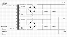
I have one power supply (toroidal transformer, rectifier, capacitors) for each amplifier. The soft-start circuit is common to both, on the primary side of the transformers.If it is an amplifier, then are using one power supply for two amplifiers (stereo)?
Yes - exactly. See attached.Are you using two separate power transformer secondary windings and rectifying/filtering them independently so that you can use a "quiet end" star point for the pos and neg supply grounds?
Attachments


Last edited:
This is what I use, +-20mF per channel allows good LF extension into 8ohms speaker........ my commitment in this direction will not go much beyond the investment in 4x 10 mF capacitors (for each mono channel). So at this point - I am trying to benefit from cheap 'tricks of the trade' or small improvements.
use one relay to bypass the soft start resistor, but make it a double pole version. Use two resistors, one to each transformer, then the double pole relay can switch across these resistors separately.I have one power supply (toroidal transformer, rectifier, capacitors) for each amplifier. The soft-start circuit is common to both, on the primary side of the transformers......
Have you seen my posts showing how I arrive at a suitable resistor value?
Last edited:
Your transformer wires look like solid core with a thin plastic tube insulator slid over. These can fatigue and break.
Replace them with a 1.5 sqmm flexible pair.
You can strip the cores from an old mains cable and just twist them together to make a good FLEXIBLE leadout about 200mm long.
These will have ~2.5milli-ohms of resistance each. If during abuse they were asked to pass 20A continuously they would each dissipate ~1W through the insulation. They would get warm, eventually. Based on this you may want to consider using a smaller gauge of flexible, 1sqmm, or even 0.75sqmm.
This extra resistance increases the resistance of the r in the rC that I mentioned a while back. It makes for a more effective filter.
Last edited:
Because you are building a dual mono (two channel) amplifier you may find that the Main Audio Ground to Chassis Safety connection creates extra noise from your amplifiers.
Be prepared to insert a Disconnecting Network (DN) into each Safety connection. This DN can have an optional switch to bypass the DN and make a direct connection.
Remember that the mains input Protective Earth (PE) wire MUST be permanently and directly, mechanically fixed to the Chassis.
Be prepared to insert a Disconnecting Network (DN) into each Safety connection. This DN can have an optional switch to bypass the DN and make a direct connection.
Remember that the mains input Protective Earth (PE) wire MUST be permanently and directly, mechanically fixed to the Chassis.
Excellent advice - thanks.
The transformer shown was destined for scrap, it's 30 years old and 625VA. I have ordered two replacement transformers of 420 VA which are also smaller diameter. I did notice that CW (the manufacturer) fits stranded leadouts... I won't mess with Terry's wiring.
I have a couple of extra bridge rectifiers that I planned to adapt into a Disconnecting Network. Can you recommend an appropriate type of 100nF capacitor?
The more you splay the forward/return wires for any current loop, the more chance of noise egressing to your audio. General twisting of all loop wires keeps the wores close, and also minimises capacitance coupling as well.
Resistance is a simple, easy way to implement impedance for 'separating' the filter capacitors. A resistor provides defined attenuation with very little in the way of parasitics, but more attenuation means more power loss in a higher resistor value, and more heating of the electrolytic caps through conduction. One option is to buy a batch of the lowest resistance 1-3W metal films, and parallel up 5-10 or so and fit between each capacitor terminal link.
You are likely to get less rectifier-induced noise by buying a batch of UF5404, and paralleling say 3 for each bridge 'diode'. Plus have a go at tuning up a snubber for each secondary winding. And then carefully locating those devices.
No and no. If the inductor was effective at lower frequencies (which it is not) then it would reduce the AC component of the charging pulses and so reduce the ripple by a small amount. As it is it will do almost nothing; it certainly won't increase ripple.cbdb said:Won't the inductor choke the charging pulses ( which have a lot of higher freqs ) and increase your ripple?
No they won't. The inductor he is proposing is too small for that. Low order harmonics will be unchanged. Only the higher order (and thus much smaller in amplitude) harmonics will be reduced. Basically, he is splitting the charging pulse between two caps and putting nearly half of the charging current through an air-cored inductor. Fine, provided that the audio circuit is sufficiently far away to avoid magnetic induction.trobbins said:popchops, the harmonic magnitudes of the current passing through the diodes will drop off rapidly from the fundamental (2x mains f).
Good audio PSU design requires that the charging pulse loop should have as small an area as reasonably possible. This idea has the opposite effect.
The cap does not add anything to the Fault passing performance of the DN. It is there only to pass interference to the enclosure.Excellent advice - thanks.
The transformer shown was destined for scrap, it's 30 years old and 625VA. I have ordered two replacement transformers of 420 VA which are also smaller diameter. I did notice that CW (the manufacturer) fits stranded leadouts... I won't mess with Terry's wiring.
I have a couple of extra bridge rectifiers that I planned to adapt into a Disconnecting Network. Can you recommend an appropriate type of 100nF capacitor?
If can be any short leaded nF cap, typically 10nF to 100nF
Similarly the resistor is only to make the "floating" audio circuits at virtually the same voltage as the enclosure. It just passes the leakage current passing from the primary to the secondary. Any value from 2r2 to 22r and low power seems to do the job.
It is in parallel with these that you can add the optional switch.
DF96, I was referring to the basic rectified half-sine periodic waveform passing the diodes, which has a reducing harmonic magnitude profile.
OK, you were saying that higher harmonics would already be small even without his inductor? Sorry for misunderstanding.
- Status
- Not open for further replies.
- Home
- Amplifiers
- Power Supplies
- Damped LC filter for low pass (1500Hz) filtering