If you mean "musical" I agree with you. Aikido is not musical at all. But this is a plus for a front-end of the main amplifier.
I don't want to bother here where we are supposed to deal with NHB-108. Perhaps I will open a thread "Warmth of the Sound" but I need to collect and write some material to show what I am talking about.
I don't want to bother here where we are supposed to deal with NHB-108. Perhaps I will open a thread "Warmth of the Sound" but I need to collect and write some material to show what I am talking about.
Erlend Sæterdal Hello, what amplifiers do you have and where in the list of Dartzeel? Do you really not like HE?🙁
The circuit of Marino is more powerful
Attachments
-
 dartzeel-amp-schematic-build-wots-wha-217.jpg951.4 KB · Views: 1,975
 -
 1500W.gif28.6 KB · Views: 1,561
 -
 468.jpg144.7 KB · Views: 1,209
 -
 23-55-51-1019dart.bac.jpg182.2 KB · Views: 959
 -
 1632433024988.jpg290 KB · Views: 917
 -
 1634862178459.jpg266.6 KB · Views: 827
 -
 2 Goldmund Telos 3300 NextGen单声道后级放大器.jpg177.9 KB · Views: 785
 -
 瑞士goldmund 高文 nextgen系列放大器.jpg112.2 KB · Views: 745
 -
 1 CH Precision M1.jpg93.8 KB · Views: 744
 -
 2 CH Precision M1.jpg77.7 KB · Views: 1,302
The circuit of Marino is more powerful
You are referring to an old version, do not attempt to make it work, or to improve your skill on it, it had some critical issues, and was hard to replicate. I re-post here the last version drawn in a well-readable way. I have now two of them, one with 11 final pairs and the other with 15, running all day long on different floors, one in the living room, the other in the basement. It is easy to replicate, no way you can fail.
It is not that hard to build if you buy the bare NHB-108 Chinese clone PCB, and the servo board, but an advanced skill is needed both in Electronics and in Mechanics.
I tested it up to 156V, this is the rectified voltage I get using the variac, but there is no reason it can work with a much higher voltage by substituting the pre-driver transistors. It could be pushed easily to deliver 400W/8Ohm.
The other schematic you posted is a lot more powerful, about 730W/8Ohm.
Attachments

Last edited:
I started a new thread "Warmth Of The Sound" here.
https://www.diyaudio.com/community/threads/warmth-of-the-sound-wots.380373/
https://www.diyaudio.com/community/threads/warmth-of-the-sound-wots.380373/
Hello,Succeeded
View attachment 789827
Yes now it is very very good. Changed input capacitor to Kasai 50 uf 63 v bipolar. Input resistor 100 ohm 0.01 % Vishay. Emitter resistors to Ohmmite. Kasei 100 uf 100 v to Nichicon 470 uf 100 V. Play like a dream. But it was hard work. Several modifications before it got good.
I bought the same board as you, can you tell what parts you have replaced? the part numbers on the board? any issues with replacing the resistors 5w 50 mohms with ohmite .22ohm? please advise.
@Legis: Overall, which do you prefer, the Goldmund clones or the Dartzeel?Did some tweaking.
0,6w resistors are Vishay MBB0207
2-5w resistors are Vishay RS wirewound
47pf and 150pf caps are Kemet C0G
Big supply caps are long-life Epcos B41560 62,000uf
Local 47uf and 330uf lytics are Vishay 150 RMI / 136 RVI
"Magic diodes" are schottky Vishay SB160
Removed the voltage stabilizing cards for the input transistors, whole cards are now driven with the same supply, no regulation (I think this is how it's done in the original also?).
As for the input transistors, I accidentally cracked one 5551 leg while pushing them agains each other (for thermal coupling)😱. I decided to change all of them to MPSA42/MPSA92. Ordered 100pcs of both (Central Cemicondictor's offering) from Mouser and to my surprise they were all VERY close tolerance, like inside 5%, almost no need to match them.😱 hFE of MPSA42/92 was 115 while 5401/5551 had around 185.
Now the DC offset is very well behaved and I could remove the DC capacitor from the feedback loop alltogether. DC-offset wanders from cold to warmed up a little but stays below +/- 20mV all the time without optimizing it for the warmed up state. It's very constant and does not "oscillate".
The MPSA42/92 seem to be more linear at low current/voltage operation than 5401/5551. I have bypassed the power-on button with a 0,1uf cap so there is always a little voltage inside the amp. With the MPSA42/92 I can now listen with the amp (at very low volume) with only +/- 0,8Vdc operating voltage. It produces sound perpetually with this low operating voltage, quite amazing😀
The amp is now at it's simplistic form. The soft-start is manual instead of a relays. There is no SP-protection relay (maybe I should put 0,1ohm/2w resistor in series with the supply caps as a "high linearity fuse"🙄). There's only the transformers, diode bridges, big supply caps and the amplifier cards, just the way I like them best.
I like this amp's relaxing and high resolution DNA. With low-esr lytics, short wiring, double output pairs and without the DC-cap the bass is also very good, almost as dry as my DC-connected Goldmund Mimesis clones.

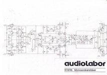
Audiolabor Stark / Studer B750
Attachments


The technology of the driving diodes should not change anything and the Vf of the SB160 is, more or less the same as any silicon diode. It would be very interesting, instead, to try a couple of Schottky diodes with a much lower Vf; you have a wide choice searching by Mouser's or DigiKey's engines; do not choose any diode with a Vr lower than the SB160.Did some tweaking.
"Magic diodes" are schottky Vishay SB160
A lower Vf diode will move the transition zone of the final stage to a lower voltage threshold, so you should get a higher DF at low power, and lower distortion.
I cannot try the mod because I use a modified 108 to drive a follower, so I removed the driving diodes.
Another improvement I recommend is to remove the input capacitor, if you have an output capacitor on the preamplifier, which is shorted towards GND during the set time, by a delay function.
Caution when powering on, always use a fuse and use a variac or a suitable couple of drop resistors and keep them when driving towards the maximum power until you finish the test.
If you like, try the mods and keep us posted.
Hello can I use just 4 transistors as out put with low supply voltage?????????2oz/ft2 after all?
What IF 🙂 one used these very wide tracks, do you think 2oz/ft2 could work, after all?:
2sc5200 and 2sa1943 transistor amplifier circuit diagram - Electronics Help Care
Maybe even I, with Zero experience, could design the portion of a board that includes your RED modifications after the Q13 and Q14 transistors, including power transistors, temperature sensors, output coil, resistors and capacitors. I e most of your WHA-217 if it is combined it with a slightly modified Chinese NHB 108 board, as per your description. If 2oz/ft2 boards could be used the WHA-217 "Extension card" would not be expensive if ordered from the Chinese company I referred to in an earlier post. PCB Prototype & PCB Fabrication Manufacturer - JLCPCB
The 108 is conceived to have no Re's on its final pair. If you add another or more final pairs you are forced to use the Re's and the foundation of the project will be thwarted.

Hi all. I want to increase the quiescent current, since the radiators heat up to only 40 degrees and allow you to increase it, their area is large. How is it easier to measure the quiescent current of the amplifier and which resistors are better to change.
hope it sounds as good as it looks !Did some tweaking.
0,6w resistors are Vishay MBB0207
2-5w resistors are Vishay RS wirewound
47pf and 150pf caps are Kemet C0G
Big supply caps are long-life Epcos B41560 62,000uf
Local 47uf and 330uf lytics are Vishay 150 RMI / 136 RVI
"Magic diodes" are schottky Vishay SB160
Removed the voltage stabilizing cards for the input transistors, whole cards are now driven with the same supply, no regulation (I think this is how it's done in the original also?).
As for the input transistors, I accidentally cracked one 5551 leg while pushing them agains each other (for thermal coupling)😱. I decided to change all of them to MPSA42/MPSA92. Ordered 100pcs of both (Central Cemicondictor's offering) from Mouser and to my surprise they were all VERY close tolerance, like inside 5%, almost no need to match them.😱 hFE of MPSA42/92 was 115 while 5401/5551 had around 185.
Now the DC offset is very well behaved and I could remove the DC capacitor from the feedback loop alltogether. DC-offset wanders from cold to warmed up a little but stays below +/- 20mV all the time without optimizing it for the warmed up state. It's very constant and does not "oscillate".
The MPSA42/92 seem to be more linear at low current/voltage operation than 5401/5551. I have bypassed the power-on button with a 0,1uf cap so there is always a little voltage inside the amp. With the MPSA42/92 I can now listen with the amp (at very low volume) with only +/- 0,8Vdc operating voltage. It produces sound perpetually with this low operating voltage, quite amazing😀
The amp is now at it's simplistic form. The soft-start is manual instead of a relays. There is no SP-protection relay (maybe I should put 0,1ohm/2w resistor in series with the supply caps as a "high linearity fuse"🙄). There's only the transformers, diode bridges, big supply caps and the amplifier cards, just the way I like them best.
I like this amp's relaxing and high resolution DNA. With low-esr lytics, short wiring, double output pairs and without the DC-cap the bass is also very good, almost as dry as my DC-connected Goldmund Mimesis clones.
Method for measuring the quiescent current of the output transistors in the Dartzeel amplifier?
It is a bit complicated, you have to cut the track of one collector, and solder a 0.1Ohm/1W resistor to bridge the two pieces of the split track. Be careful, the PCB is kind of delicate. Now you can measure the voltage across the resistor, each 1mV you read corresponds to 10mA. At the end of your measure, remove the resistor and bridge the split track with a piece of copper wire, the change with/without the resistor is negligible.
IMHO it is not worth it.
But, if you want to measure, you must have in mind to play with the quiescent current. Then you have to decide how you want to use your amplifier. Usually, the average power in a normal home listening is 3W on an 89db W/m speaker, so you could choose a quiescent current high enough to let the final stage operate in Class A up to, let's say, 10W, in order to remain in Class A during the small peaks. You can push the Class A even higher, up to the maximum dissipation allowed by your heat sinks for a temperature within 70C max.
But, if you plan to use your amplifier to obtain high power, you better stay in B class, with the minimum possible quiescent current.
Class A guarantees the best sound.
Class B has a sound almost like Class A when correctly trimmed.
Class AB generates some distortion in correspondence of the transition Class A / Class B, so it would be better to let the transition happen at the lowest possible level, that's why Class B is to be preferred for high power usage.
Is there a recent component list, BOM or Mouser shopping list for this project? I’ve searched for teo days now and looked over my old notes but no luck. @marigno @Erlend Sæterdal @analog_sa ?

- Home
- Amplifiers
- Solid State
- Dartzeel amp schematic - build this?