I was looking at some phono stage designs and didn't like the typical asymmetrical stack of paralleled transistors, put in the feedback loop of an op amp.
It seems super unbalanced and would be impractical to get good THD performance at low frequencies since it's all AC coupled.
So to make a simpler circuit I sketched up this overkill one.
It's a symmetrical set of szlyskai pairs; Bases tied together, which is the input.
The supplies of which are fed from a pair of op amps that give negative feedback to the circuit (all DC coupled), and also bias the circuit.
The idea being that the 2 symmetrical pairs balance the bias current. Would the noise from these being in parallel cut down on the noise?
Then there's a synthetic load, which I included in the circuit so I could ask about the noise.
In Self's book he mentioned that he had concerns about the noise from the synthetic load input going back into the signal chain. But wouldn't that cut down on the noise?
If you connect 2 op amp inputs together wouldn't the noise be the result of the sqrt of the 2 noises combined?
No. Sorry, but the noise always adds. You'll find H&H get quite heated about noise in op-amps using bias cancellation. You see, although the input offset current is significantly reduced, the noise is related to the currents before cancellation, so it tends to be rather large. Don't see why your synthesised load resistance should be a problem.
But even if the transistor is the opposite polarity, wouldn't the effective base resistance be cut in half, hence the noise voltage would be sqrt(2)?
I don't get how having an NPN + PNP in parallel arranged like this is different than having 2 NPN transistors in parallel, just single ended.
The noise current would be flowing from base to 2 locations rather than 1. But if both of those locations are lets say 0 ohms. To me it seems like the base resistance would still be in parallel, and cut the noise.
Here's one of the very oldest solid state Moving Coil preamps. It uses eight transistors in parallel: four PNPs and four NPNs, to reduce noise. The fully complementary push-pull circuit also reduces even order distortions.
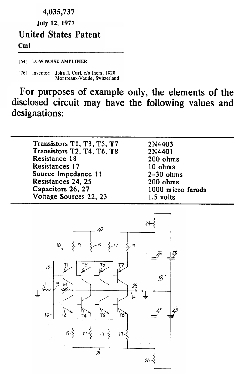

Noise voltage gets better, noise current (which doesn't matter much anyway for MC) gets worse when you parallel stages (complimentary or not).
I haven't properly analysed your circuit, but I wonder if the noise of the leftmost two op-amps and their feedback networks doesn't add to the input stage noise.
I haven't properly analysed your circuit, but I wonder if the noise of the leftmost two op-amps and their feedback networks doesn't add to the input stage noise.
Indeed. The variances add, so the RMS noise current (= standard deviation, if ergodic) increases by only square root of two when you parallel two independent noise current sources with equal probability distributions.
I wrote a more elaborate answer to a similar question last year, see https://www.diyaudio.com/community/threads/oread-a-diy-mm-phono-approach.406480/post-7534798
I wrote a more elaborate answer to a similar question last year, see https://www.diyaudio.com/community/threads/oread-a-diy-mm-phono-approach.406480/post-7534798
But would the complimentary input stage actually have less noise than a single ended one?
I think so but all the low noise amplifier circuits I've seen have been mostly single ended.
So I'm not sure...
Anyone got any experience with this?
Also, how does the required extra circuitry with a single ended design come into play? Since you'd need a CC source or collector resistor, that would add some noise. But in my design it's complimentary so it increases the amplification factor.
Last edited:
It depends.edgarsls said:But would the complimentary input stage actually have less noise than a single ended one?
Noise goes up by sqrt (2). If the output signal goes up by 2x, then the S/N improves. If the output signal remains unchanged, the S/N becomes worse.
Ed
Since the output goes to a Riaa amp, I suppose this circuit is supposed to be thought as a headamp for an MC cartridge.I was looking at some phono stage designs and didn't like the typical asymmetrical stack of paralleled transistors, put in the feedback loop of an op amp.
It seems super unbalanced and would be impractical to get good THD performance at low frequencies since it's all AC coupled.
So to make a simpler circuit I sketched up this overkill one.
It's a symmetrical set of szlyskai pairs; Bases tied together, which is the input.
The supplies of which are fed from a pair of op amps that give negative feedback to the circuit (all DC coupled), and also bias the circuit.
The idea being that the 2 symmetrical pairs balance the bias current. Would the noise from these being in parallel cut down on the noise?
Then there's a synthetic load, which I included in the circuit so I could ask about the noise.
In Self's book he mentioned that he had concerns about the noise from the synthetic load input going back into the signal chain. But wouldn't that cut down on the noise?
If you connect 2 op amp inputs together wouldn't the noise be the result of the sqrt of the 2 noises combined?View attachment 1349204
So why adding a synthetic load where a simple termination with a resistor is adequate ?
Also the DC current through the input pairs seems to me completely uncontrolled.
Hans
Well you could trim the DC current just by shifting the bias voltages. Oh and it's probably a better idea to use a pair of diodes and run current through them for the bias voltage, rather than a resistor ladder which would be a nightmare to adjust.
Couldn't get a spice sim running tho, every op amp model seems to just oscillate no matter what with this design
I ditched the szliskai pair since I realized there's voltage across the transistors is limited to 2Vbe. And adding diodes on the input would increase the base resistance.
Couldn't get a spice sim running tho, every op amp model seems to just oscillate no matter what with this design
I ditched the szliskai pair since I realized there's voltage across the transistors is limited to 2Vbe. And adding diodes on the input would increase the base resistance.
The input-referred voltage noise increases by 3dB with differential input stage compared to single ended, and the input-referred voltage noise goes down by 3dB with a paralleled input stage (such as complementary) compared with single device - you just have to figure out which topology applies to your circuit by drawing out the noise sources explicitily (or using Spice!)Noise goes up by sqrt (2). If the output signal goes up by 2x, then the S/N improves. If the output signal remains unchanged, the S/N becomes worse.
The gain of the amp doesn't affect S/N if the input stage is the limiting factor for noise (which it should be).
Hi Mark,The gain of the amp doesn't affect S/N if the input stage is the limiting factor for noise (which it should be).
Might be it's good idea to explain it on forum, for many rookies like me.
In my understanding , considering one gain device, aka amplifier:
- any source noise is proportionally amplified as signal is, so Snr from that point is unchanged
- amplifiers input noise voltage is more or less constant regardless of gain, so higher gain will yield better SNR of the system.
Dražen
Hi,
No, did not mean that, just if we imagine one gain device with given input noise, what's relation of SNR vs gain?
I my view SNR is better with raising gain as noise raises if at all less than signal
No, did not mean that, just if we imagine one gain device with given input noise, what's relation of SNR vs gain?
I my view SNR is better with raising gain as noise raises if at all less than signal
And that's how John Curl's moving coil preamp (1977) in post #4 above, achieves lower noise. Four NPNs and four PNPs, with all eight bases connected, form an input pair. Additionally, the fact that they are arranged in a symmetric push-pull configuration, reduces even order distortions as well.Maybe for completenes to add to the above: a NPN and a PNP used as input pair with their bases connected, also reduce the input noise by 3 dB, just as two parallel transistors.
Hans
I hope to understand what you mean.Hi,
No, did not mean that, just if we imagine one gain device with given input noise, what's relation of SNR vs gain?
I my view SNR is better with raising gain as noise raises if at all less than signal
There are two scenarios, inverting and non inverting.
Starting with the inverting first, assuming the feedback resistors are noiseless, and
say input noise is A.
Now for a 1x inverting amp, with equal resistors for Rf and Rg, absolute gain for signal S is 1 but noise gain as caused by the positive input is 2A.
So S/N referred to output is S/2A
Now increasing the gain to 100 gives a S/N of 100S/101A.
So indeed when raising the gain will improve S/N, but this falls rapidly to insignificant advantages.
Now for a non inverting amp.
With a gain of 1, signal output is S and so is noise gain A.
S/N is S/A.
At a gain of 100, S/N is 100S/100A, this time independent of gain.
To complicate things a bit is that Rf//Rg also produce noise, adding to the amps input noise.
So the higher Rf with fixed Rg, the more noise will be added in both inverting and non inverting topology, potentially worsening the S/N, but also being rapidly dominated by Rg when increasing gain.
That’s why Rg should be kept as low as possible.
Hans
- Home
- Source & Line
- Analogue Source
- DC MC low noise input stage with Bias Cancellation idea