Actually, this prompted me to some more searching. I had used for the brand names Telar and Armco, but searchign for "Reineisen" = pure iron revealed
www.angele-shop.de
The sell various formats of round, angular rots as well as flat sheet of pure iron with a carbon content of 0.01% max. at 5 €/kg for small quantities.
www.angele-shop.de
The sell various formats of round, angular rots as well as flat sheet of pure iron with a carbon content of 0.01% max. at 5 €/kg for small quantities.
Thanks again for your input Suranjan Das Gupta,
I appreciate for your time answering my questions!
Eric (Capslock),
interesting stuff you have come up with regarding diffrent iron grades.
btw, what stands PU for, some enamel or is it really some polymer?
While we are on the subject motor I would also like to know more about these shortcircuit rings used somewhere around the center pole or so.
How does it work?
What are the benefits with it?
What kind of diffrent type of shortcircuit ring technics are there?
What are the drawbacks and what kind of parameters change in what direction and how does it affect?
I think i red somewhere that someone copperplated the edge of the pole gap or so, but how could that give any benefits since the iron itself is conducting also current, I thought the shortcircuit ring should be isolated from the pole parts or maybe I just remeber wrong.
I have weak memory that Peerless had some patent on shortcircuit rings for the motoralready for at least 15 years ago I think, does anybody know what it is?
Regards Michael
Michael,
PU = polyurethane.
do a search on Faraday rings, short circuit rings in this forum, it's been discussed often enough.
In short, the AC field of the voice coil (VC) modulates the magnetization of the pole piece. This gives rise to two effects:
- the pole piece acts as an iron core to the VC, increasing its inductance, and this inductance will be a function of excursion (because the pole piece fills the VC only partially) and drive level (the magnetization is nonlinear)
- the field in the gap will be modulated nonlinearly because of the nonlinear hysteresis curve of both iron and ferrite magnet
The AC field of the VC will also induce a mirror eddy current in the pole piece. Copper has 20x higher electric conductivity, so if the pole piece (or preferably the full inside of the VC) is covered with a copper cylinder, the eddy currents will be largely confined to the 0.5 mm or so of copper rather than 10 mm of iron. So the iron sees a much more constant field, hence abovementioned effects are attenuated.
As for patents, have a look at:
DE 2362001 C2 by Ragnar Lian (depatis.net will let you do a search and download)
US815587 A1 by Lars Goller (Scan Speak)
DE3046551 C2 (Isophon)
hi
Shorting Rings are applied for :-
When a vc moves in a magnetic field
1) taking the upward movement as + ve half of a wave and downward stroke as the negative half of the wave
the inductance of the voice coil changes
as in the inward stroke it moves physically into the magnet (motor) encircling it , and in the +ve upward stroke it physically moves away from the magent
with this changing inductance you will get different spl s fror a particular frequency in the +ve half compaired to the -ve half of the wave form
- this also generates - uneven dc components in the vc leading to distortion
2)
when a vc moves in a magnetic field it generates eddy currents in the pole material
which in turn will influence the vc and generate distortion
These are the most common types of shorting rings
a) A copper cap
b) A copper ring around the T of a pole piece in a symmetrical motor
c) Alumunim Ring embedded below the T of a symmetrial motor (this will be at varieng distances from the top of the pole piece (situated atop the bottom plate)
d) Alumunim sleeve around the inside of a magnet - the sleeve fully shorted touching both the top and bottom plate
e) the above soldered to a wire brought put of the bottom plate and grounded
f) a copper cup shaped ring shorting the top plate to the pole - with the vc embedded in this cup ( in the magnetic gap)
Capslock
I agree 0 % is totally dependant on the measuring tools , the sweat & minerals theaory is from a Dr. Becks study - I think one of the worlds largest manufacturere of polymide & polyurethane insulation materials - though with changing material science the study may be out dated
Suranjan Das Gupta
Hi Eric,
thanks for your patent numbers, unfortunately I don't manage to make search on these numbers.
WWW.DEPATIS.NET doesn't seem to work.
German espacenet does not regognize the german patent number DE 2362001 C2.
the USPTO does not recognize US815587 A1
I have searched the net for some other patent search sites and tried these numbers but I give up after half hour without result, would you be kind and find out where to find these patents on the net?
Hi,
Thanks for your input, I have done some research and searches also for that matter on this forum, but new questions arises.
What is the critery of selection of iron grade, highest possible flux density or else? Are there some issues with some kind of "linearity" in diffrent iron grades? And how about Barkhausen noise, is it important too? Are there other issues with iron materials?
Same questions as above applyed to the selection of diffrent magnet materials, what has to be concidered?
Suranjan Das Gupta,
You gave couple of examples how the shorting ring or Faraday ring can be applied in a motor design.
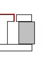
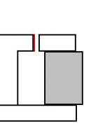
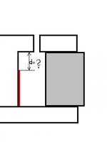
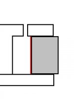
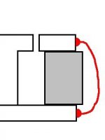
I have made up some sketches to try to visualize your examples from 'A' to 'E', 'F' did I left out because I'm not sure what you mean. However, did I got my pictures right?
I have some questions what is the real issue when using a shorting ring, I mean where exactely those the "problem" occure to be cured?
Is it a major problem at the magnet gap where the top plate and center pole meet each other?
Is it only the pole peaces that suffers from the drewbacks or is the problem also in the magnet also?
I have red that Neodymium magntes are conducting material so there seem to be a smaller problem with Neodymium.
Is it only Barkhausen noise or are there other phenomenoms in magnets as well as in iron?
Is Eddy current a problem, and if so is it only in iron or is it also a problem in magnets too?
Regrds Michael")
PS: I'm not sure how to upload several pictures in one post so picture 'A' will be shown here first.
If somebody now how to upload several pictures in a singel post, please reply or send a PM, thanks in advance!
The red color in all picture is the copper(or Alu or whatever..) shorting.
Thanks for your input, I have done some research and searches also for that matter on this forum, but new questions arises.
What is the critery of selection of iron grade, highest possible flux density or else? Are there some issues with some kind of "linearity" in diffrent iron grades? And how about Barkhausen noise, is it important too? Are there other issues with iron materials?
Same questions as above applyed to the selection of diffrent magnet materials, what has to be concidered?
Suranjan Das Gupta,
You gave couple of examples how the shorting ring or Faraday ring can be applied in a motor design.
I have made up some sketches to try to visualize your examples from 'A' to 'E', 'F' did I left out because I'm not sure what you mean. However, did I got my pictures right?
I have some questions what is the real issue when using a shorting ring, I mean where exactely those the "problem" occure to be cured?
Is it a major problem at the magnet gap where the top plate and center pole meet each other?
Is it only the pole peaces that suffers from the drewbacks or is the problem also in the magnet also?
I have red that Neodymium magntes are conducting material so there seem to be a smaller problem with Neodymium.
Is it only Barkhausen noise or are there other phenomenoms in magnets as well as in iron?
Is Eddy current a problem, and if so is it only in iron or is it also a problem in magnets too?
Regrds Michael
PS: I'm not sure how to upload several pictures in one post so picture 'A' will be shown here first.
If somebody now how to upload several pictures in a singel post, please reply or send a PM, thanks in advance!
a) A copper cap
The red color in all picture is the copper(or Alu or whatever..) shorting.
Attachments
b) A copper ring around the T of a pole piece in a symmetrical motor
Attachments
c) Alumunim Ring embedded below the T of a symmetrial motor (this will be at varieng distances from the top of the pole piece (situated atop the bottom plate)
Attachments
d) Alumunim sleeve around the inside of a magnet - the sleeve fully shorted touching both the top and bottom plate
Attachments
e) the above soldered to a wire brought put of the bottom plate and grounded
Attachments
I would suggest reading this: http://ldsg.snippets.org/motors.php3 and perhaps the Loudspeaker Design Cookbook by V Dickason.
Thanks Vikash for the link,
no offence but it was a nice link with perhaps not so much food, i still missing deeper physical insight to my questions.
however I have partially found some information by googling and also by searching this forum, but still would like to know more, hopefully somebody would like to answer my questions in post #26. .
I wonder why Scanspeak with their SD-1 motor design don't cover the iron at the air gap with copper, it seems odd to me.
At least as far as I could see in the picture given here.
If i am not completly wrong I belive the Loudspeaker Design Cookbook by V Dickason they do not go into deeper physics regarding the motor design, but surely a comprehensive book for loudspeaker builders who want to digg deeper into that subject.
Regards Michael
When you put copper in the gap, it means you can use less iron. Less iron means lower flux (-10-15% for 0.5 mm wider gap), hence you get lower sensitivity and a lower ratio of peak flux vs. stray field flux. The latter means you get a worse Bxl linearity. So it is partly about a trade off of static linearity vs. midrange linearity.
Another argument in the Goller patent was that you can preserve some inductance to control the rise of the frequency response. Of course, the same can be achieved by adding a series inductance in the XO, but a flat FR looks so much nicer in the data sheet....
Another argument in the Goller patent was that you can preserve some inductance to control the rise of the frequency response. Of course, the same can be achieved by adding a series inductance in the XO, but a flat FR looks so much nicer in the data sheet....
Hi
Capslock - could you provide me the Link to the above Info - That Copper in Magnetis Gap reduces Flux and obviously in turn BL
Or you can email it to me at tubu_cruise@yahoo.com
Thanks
Suranjan Das Gupta
Capslock - could you provide me the Link to the above Info - That Copper in Magnetis Gap reduces Flux and obviously in turn BL
Or you can email it to me at tubu_cruise@yahoo.com
Thanks
Suranjan Das Gupta
I think it's just straight geometry. If you copper-line the gap, and you must maintain the same clearances from the voice coil to the gap, then you must shave away steel. From a flux standpoint, copper is the same as air. Since there's copper where there was steel, the gap is now wider, meaning less flux flow.
This is why many designs use copper/aluminum above and below the gap, but not in the gap. Keep the flux, and try to reduce as much of the inductance and flux modulation as possible.
We've occasionally added copper into the rebates on our XBL^2 motors, so that we can partially fill the "gap" without a loss in flux (the steel is already cut away, so we're only "displacing" air with copper, not steel with copper).
Dan Wiggins
Adire Audio
hunter audio said:Hi
Capslock - could you provide me the Link to the above Info - That Copper in Magnetis Gap reduces Flux and obviously in turn BL
Or you can email it to me at tubu_cruise@yahoo.com
Thanks
Suranjan Das Gupta
Dan has already answered your question. I had a thread on asymmetrical voice coil windings in an old Peerless CSC driver that was last active about two weeks ago. It contained flux simulations, and I also simulated shaving off 500 µm of steel and had a flux loss of about 15%.
Hi
Dan I agree , This is as per my findings that copper will not reduce the flux / or intefere
I agree totally with the geometry factor ,
Infact if we short the gap with a Copper Cup - Top Plate to Pole -the gap is totally saturated
( Inserting the rebates - requires some tactful machining )
Suranjan Das Gupta
Hi
Capslock I have machined - shaved off all types of materails but hardly got a drop of 15 % in real life in the range of your values -
can you discharge some of your motor structures (after measuring accurately intially the motor strength) and then shave of the top plate and reassembe the same motor - charge and measure again - to ascertain the accuracy of your simulation software
you need to do this with the same motorstructure - not two sets of top plates with different bores for accuracy
This is our machining procedure -
1 ) First - Lathe ,
2 ) Then Surface Grinding the face plates ,
3 ) Then sand blasting the Magnet Assembly Face ,
4 ) Then finally Bore Grinding to the Gap width / Gap OD
as for the copper in flux i had no doubt about the reduction as there is no reduction - therefore i wanted to know the source as intially you had mentioned a patent article
though i do admit i may have not given your post a thorough read - sorry
suranjan das gupta
Rebates on the pole/core aren't too bad because it's an outside-in cut (just a standard polish cut on a forged piece that "polishes" a bit more at the proper location).
It can be difficult to do on the top plate, because it's an undercut "inside-out" cut. So build your top plate this way:
Stamp the inner plates with larger IDs, and you inherently have a rebate in the top plate. Also makes it REALLY simple to add a ring of copper or aluminum in that rebate - stack the bottom and middle plates, drop in the ring, then stack the top plate.
FWIW, about 90% of all XBL^2 drivers use laminated stamped top plates, because of the ease of assembly and low cost (stamping is really low cost compared to forging).
Dan Wiggins
Adire Audio
It can be difficult to do on the top plate, because it's an undercut "inside-out" cut. So build your top plate this way:
An externally hosted image should be here but it was not working when we last tested it.
Stamp the inner plates with larger IDs, and you inherently have a rebate in the top plate. Also makes it REALLY simple to add a ring of copper or aluminum in that rebate - stack the bottom and middle plates, drop in the ring, then stack the top plate.
FWIW, about 90% of all XBL^2 drivers use laminated stamped top plates, because of the ease of assembly and low cost (stamping is really low cost compared to forging).
Dan Wiggins
Adire Audio
- Status
- This old topic is closed. If you want to reopen this topic, contact a moderator using the "Report Post" button.
- Home
- Loudspeakers
- Multi-Way
- Designing Own Speaker Elements