How the Diaphragm(s) where configured, one only was defined or 2, 1 for front and 1 for rear?I use FreeCad + Gmsh and it's a single subdomain (that's usual but it works for shallow open designs like this).
I made similar toroid simulation, but not get reasonable result with front and rear side diaphragm defined.
Just to remind you sim-guys... before you go too long with this, don't forget to add spider, basket frame, coil and magnet/motor structure on the backside. As well on the frontside there is dustcap with varyng dimensions and profile ant the surround roll
These all very much do affect the frequency response "distribution" on- and off-axis at frequencies higher than first axial dipole null. Real life measurements with some specific driver will always be different from simulations!
Here is a video of a pro sim to design cone and dustcap midwoofer (and only the frontside!) FINECone™ | Acoustic Finite Element Dome/Cone Simulation Program
FINECone Demo - YouTube
Last edited:
Just to remind you sim-guys... before you go too long with this, don't forget to add spider, basket frame, coil and magnet/motor structure on the backside. As well on the frontside there is dustcap with varyng dimensions and profile ant the surround roll
These all very much do affect the frequency response "distribution" on- and off-axis at frequencies higher than first axial dipole null.
Didn't Don's sim model most of that? And it begs the question, how much do these things matter to the end result, what are the priorities of a dipole design?
A major plus seems the elimination of box effects which would go some way to explaining the lack of interest in using back to back monopoles.
How the Diaphragm(s) where configured, one only was defined or 2, 1 for front and 1 for rear?
I made similar toroid simulation, but not get reasonable result with front and rear side diaphragm defined.
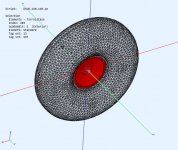
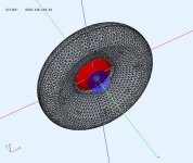
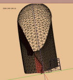
I use the built in Diaphragm generator. So it has the basic parts : 2 sided cone (front, rear), voice coil, magnet, and dust cap for the BEM side. The electrical side uses the LEM model for T/S parameters.
Try separating the front and rear cone sides by a small amount (5mm) using either "shift" or "t1".
Are you using ABEC or AKABAK for your model?
Just to remind you sim-guys... before you go too long with this, don't forget to add spider, basket frame, coil and magnet/motor structure on the backside. As well on the frontside there is dustcap with varyng dimensions and profile ant the surround roll
These all very much do affect the frequency response "distribution" on- and off-axis at frequencies higher than first axial dipole null. Real life measurements with some specific driver will always be different from simulations!
Here is a video of a pro sim to design cone and dustcap midwoofer (and only the frontside!) FINECone™ | Acoustic Finite Element Dome/Cone Simulation Program
FINECone Demo - YouTube
Thanks @juhazi that's a great video showing the driver misbehaving at higher freq. The S/W is way out of my price range ($8K) and is aimed at driver development. I don't attempt to include or reproduce frequencies where the driver misbehaves or breaks up. A real driver will show more differences if it pushed to misbehave.
Yes I was happy to be informed that AKABAK has motor and dustcap structure included. Anyway, at the high frequencies they make interferences, very small differences matter.
If you look at the pics I posted you can see the cones, dustcap, magnets and voice coil. The model assumes they are stiff.
Last edited:
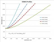
This is a continuation of the torus OD=450mm except 140deg OSWG are used for the exit profiles. It has a similar driver offset and exit areas to the previous torus Did Siegfried Linkwitz miss a trick?
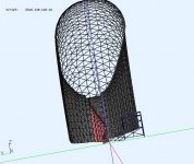
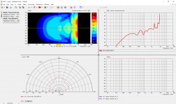
Looks like it could use some more tuning. I was expecting to see less HF ripple. The driver exit profile (140deg OSWG flare) is the same on both sides, but due to the driver offset, it expands to a larger opening on the rear side.
.
Looks like it could use some more tuning. I was expecting to see less HF ripple. The driver exit profile (140deg OSWG flare) is the same on both sides, but due to the driver offset, it expands to a larger opening on the rear side.
.
Attachments
-
 OSWG-profiles.jpg69.5 KB · Views: 196
 -
 Torus-OSWG140-Front.jpg69.4 KB · Views: 203
 -
 Torus-OSWG140-Rear.jpg63.1 KB · Views: 201
 -
 Torus-OSWG140-Xsection.jpg58.4 KB · Views: 204
 -
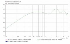 Torus-OSWG140-FR@3m.jpg33.4 KB · Views: 199
 -
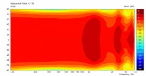 Torus-OSWG140-Polar@3m.jpg26.1 KB · Views: 68
 -
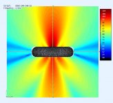 Torus-OSWG140-ObsField@4000Hz.jpg36.2 KB · Views: 64
 -
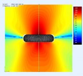 Torus-OSWG140-ObsField@2100Hz.jpg34.7 KB · Views: 60
 -
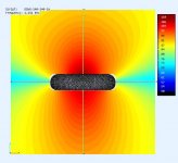 Torus-OSWG140-ObsField@1200Hz.jpg33.7 KB · Views: 56
 -
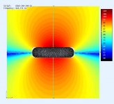 Torus-OSWG140-ObsField@500Hz.jpg34.5 KB · Views: 64
I am using AKABAK 3.I use the built in Diaphragm generator. So it has the basic parts : 2 sided cone (front, rear), voice coil, magnet, and dust cap for the BEM side. The electrical side uses the LEM model for T/S parameters.
Try separating the front and rear cone sides by a small amount (5mm) using either "shift" or "t1".
Are you using ABEC or AKABAK for your model?
I made nearly similar BEM and LEM with T/S, 2 cones. But you use some trick to get results with only one subdomain?
On other simulations I use always 2 subdomains: interior, exterior and interface plane between them.
Can you upload or send some of you torus simulation file?
^kaameelis
PM sent with a link to the project.
I use both ABEC and AKABAK, but this project was in ABEC so I converted it to AKABAK for you.
There is no trick, both sides of the driver are facing freespace so only 1 subdomain is needed. Imagine a naked driver suspended by a wire. This is an unusual case, normally I have multiple subdomains for the same reasons you mentioned.
Last edited:
Could the slower rate of opening at the edge of the driver be effecting the HF?
Maybe. I was hoping the deeper rear exit horn (larger mouth) would control the wavefront better (to a lower freq) but clearly it needs improving. In theory, the WG would reduce the diffraction and interference between the two sides at higher freq. It might be a matter of finding the right OSWG coverage angle. A few more trials
")
I'm not sure if this can be tried in the computer model but we have seen that the use of an absorbent material (like felt) on the face of normal flat baffles can be of benefit, what would happen if a similar material was added to the surface of the torus? and with an irregular shape, or density? (star pattern cutout around tweeters, for example)
And if some absorbent material was added to the outer edge (were the front and rear waveform meet), and if this also had an irregular profile, would this effect the low freq behavior?
And if some absorbent material was added to the outer edge (were the front and rear waveform meet), and if this also had an irregular profile, would this effect the low freq behavior?
^james
Yes I can change how absorbent the surfaces are, to see the effect. Although I still think there are other issues causing these problems. Felt may help attenuate the HF but maybe not so good for LF. If the embedded horns work, there would be little energy left at the edges.
Yes I can change how absorbent the surfaces are, to see the effect. Although I still think there are other issues causing these problems. Felt may help attenuate the HF but maybe not so good for LF. If the embedded horns work, there would be little energy left at the edges.
Can you try a shallow conical waveguide like this?
The more shallow the contour, the wider the coverage. So that drawing (moustache ?) would need to increase coverage from 140deg to 160deg. I was thinking of reducing the coverage to 100-120deg to have even more focus.
Yes, Don, probably nothing in it - I wondered about it as Mattes is using a somewhat softer material that's not at all easy to work with so there must be a good reason for it - no doubt he's done much homework on this and without impinging on his design, it'd save us trying to 'reinvent the wheel'
Why would that be a problem? It would be similar to having the driver more flush with the front of the baffle.The more shallow the contour, the wider the coverage. So that drawing (moustache ?) would need to increase coverage from 140deg to 160deg. I was thinking of reducing the coverage to 100-120deg to have even more focus.
I upload my AKABAK file here. It is made basically in same way as yours, one subdomain only, but result is not reasonable....
There is no trick, both sides of the driver are facing freespace so only 1 subdomain is needed. Imagine a naked driver suspended by a wire. This is an unusual case, normally I have multiple subdomains for the same reasons you mentioned.
As it is not using symmetry and lot of elements are involved, calculation of simulations take about 5 hours. Torus shape is not very meaningful, made just for testing of Akabak simulation.
Attachments
- Home
- Loudspeakers
- Full Range
- Did Siegfried Linkwitz miss a trick?